CNC Part 4.1 - Config
This is part 4.1 of my portal milling sequel. It is tightly coupled to Part4 but specifically handles settings for the CNC software that I use.
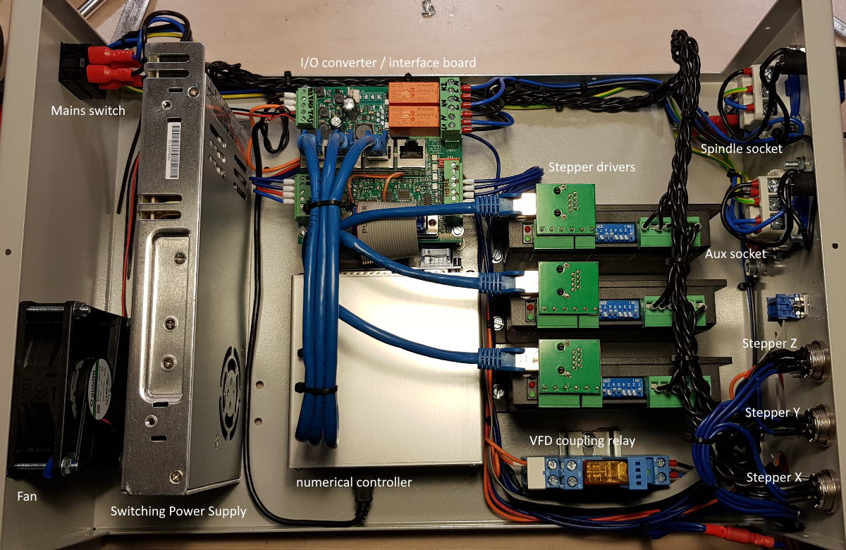
Hardware Assumptions
- EdingCnc V5A-4E processor board or similar
- Interface Advanced PRO breakout board or similar
- Adapter Board or similar
These components are necessary to translate the commands created by the CNC software into physical-world signals that can actually interact with matter. The breakout board is controlled by the CNC processor and provides relay outputs for the router and my dust collector so I can have them switched on using my laptop. There are also analog voltage outputs e.g. to control spindle RPM and multiple inputs e.g. to read reference switch status and for signaling events back to the CNC software.
Of course there are many manufacturers of these circuits out there, but I happen to be using the above ecosystem so I can only speak for those. The underlying technology is the same, and although you might have a different user interface or communication channel like USB, your software will likely provide similar if not identical settings.
Setup screen 1
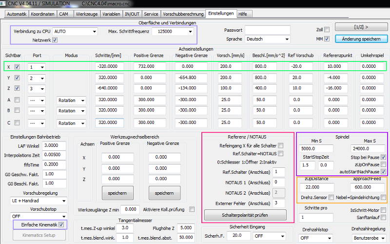
Kinematics
As discussed in-depth in this post, the green frame shows kinematics settings. A negative sign in the Steps/[mm] indicates that the stepper motor direction is inverted. Note that the reversing play field can remain 0 when ball screws are used. I’m using “simple kinematics” so the coordinate system is cartesian.
Reference / Emergency stop
This section controls how the software interptets signal levels for input switches on the interface board. Although I’m sure I wired all inputs “normally closed” to avoid undetected cable rupture, I had to invert the input for the emergency switch.
Spindle
These settings are very specific to the machine you’re using. I wanted the spindle to stop when I pause a job, and to automatically restart before continuing the job.
The approachFeedparameter is a bit confusing because the default value is really low here. Its meaning is the following: It’s the Z-axis’s downwards feed when a job had been paused and the Z-axis moved upwards. When you press “continue”, the Z-axis will be lowered with this feed and when at target depth, the job will continue normally. I entered 600mm/min as a value most endmills should be capable of dealing with.
Setup screen 2
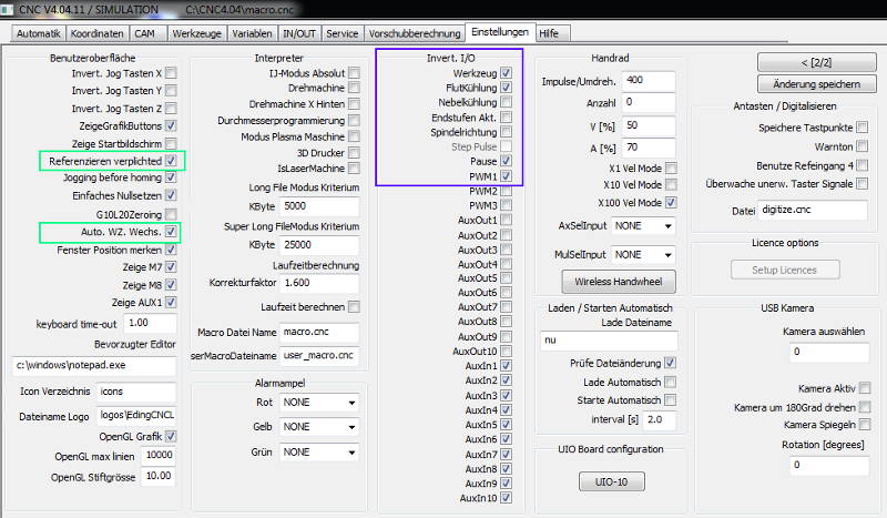
User interface
I wanted referencing/homing to be mandatory before being able to load a job or to rapid-move the machine’s axis.
I also selected automatic tool change although I don’t have a tool changer because otherwise my tool change macro helping me do the manual tool change wouldn’t be called.
Interface I/O
To account for the interface/ breakout board’s hardware setup, I had to invert some software outputs so they’d do what I’d expect them to. If I didn’t invert PWM1 for example, the spindle would start at full speed when I just wanted 5000rpm and vice versa.
Variables screen
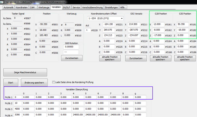
Parking position G28 / G30
I set my parking positions in a way that allow me to work more efficiently. One of these commands would make the axes move to XY-zero of my fence that I’d also make workpiece-zero in CAM so zeroing in becomes really easy.
The other one is set to a point where the reference switches of all three axes are nearly pressed so homing the machine after startup becomes both easy and quick.
Variables monitoring
Note the monitoring window. You can enter a variable from the RS274 NGC interpreter range and have their current values displayed here. This comes in handy when you want to debug macros or just want to read internal parameters like measured tool length etc.