CNC Part4 - Setup
This is the 4th part of my portal milling machine sequel. It concentrates on hardware and software setup so the portal milling machine “Zerspanobert” can be soon switched into productive mode.
- Part 1: Thoughts about CNCs in general and machine selection
- Part 2: CNC Electronics build
- Part 3: CNC Machine build
Kinematics
Before the CNC software can do any job on my BasicLine 0607, it needs to be set up correctly so it knows the mechanical ranges of the machines’ axes, where the homing switches are located, and in which direction to turn the stepper motors to yield “positive/negative” axis movement.
As a first step, a decision is needed on the machine’s axis naming (X, Y, Z), on where all axes shall effectively be 0, and movement direction (positive, negative). All those coordinate points are relative and can be chosen arbitrarily, but there are some conventions in the CNC world:
Axes:
- X-Axis is on the portal bed, moving the portal’s Y-axis.
- Y-Axis is up on the portal, moving the Z-axis assembly.
- Z-Axis is located at the spindle, moving it up- and downwards.
Machine 0-point
Machine 0 and movement direction:
- X-0 is at the “rear” of the axis. Movement direction is negative.
- Y-0 is at the “left” of the axis. Movement direction is positive.
- Z-0 is at the “top” of the axis. Movement direction is negative.
For my machine and the room setup I have, I chose the X-axis to be the portal’s long axis while the Y-axis would be along the linear guides of the machine bed. Z would be facing upwards, following the convention. I wanted the machine Zero to be in the “Top left corner”, so Z-axis would go down (-), Y-Axis down (-), X-Axis to the right (+).
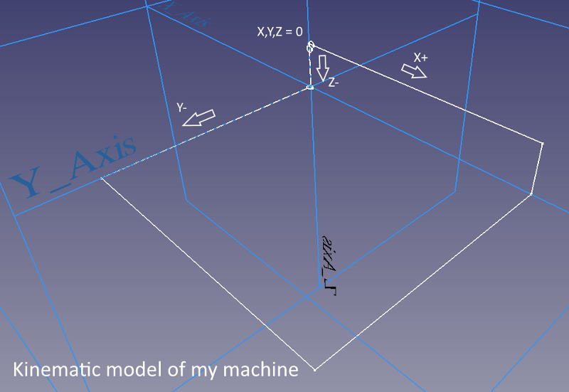
Movement directions
To get started with the configuration, I connected to my CNC software. In the Setup view, I entered the step count needed to move an axis by one millimeter: 16 microsteps/step multiplied by 200 steps/turn divided by 10mm/screw turn = 320 microsteps/mm. I took double this value for the Z-Axis as the ball screw thread is less steep here.
16 microsteps/step is the stock value recommended by the machine manufacturer. There are some good arguments and an in-depth analysis here that recommend to use less microstepping, though. As I’ll neither require 1/100mm accuracy nor see extremely high cutting forces due to the materials I’ll be working with, I just kept the stock settings here.
Without homing (which wouldn’t work yet anyways), I used the jog keys at safety speed to check which key would move which axis, and into which direction. As my setup is different from “normal” the values I chose may differ from yours. If an axis wouldn’t match the arrow-key (e.g. pressing “right” and I’d expect my X-axis to move to the right, but actually the Z-axis would go down), I’d switch connections at the switch box until the keys would match the expected axes.
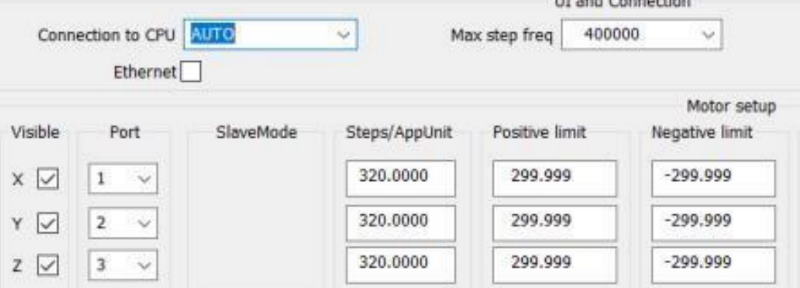
Now, if the keys would move the axis into the wrong way, e.g I press “page down” but Z-Axis would go up, I’d change the signedness of the resolution field. For the axes I now had:
X-axis -320.000Y-axis 320.000Z-axis -640.000
Machine travel
My machine has a usable mechanical travel of 0 / 732mm in X direction, -654mm / 0 in Y direction, and -134mm / 0 in Z direction. I entered these values into the mask for negative limit / positive limit and set the signedness based on the movement direction relative to machine zero.
Reference switches: Trigger level
The axes of most machines have a reference switch. These switches are used to “home” the machine. Homing is required at every machine startup because internally, the software is just inferring XYZ-position by accumulating motor steps. Once the system is restarted, all those values go back to 0 so the machine forgets its position.
I connected my switches so they are “Normally Closed”: Their contacts are conducting current when not triggered. This way, a faulty open connection can be detected immediately as the machine would home (without success) at an unusually low speed in this case: homeVelocitySlow is just 1/10 of normal homing speed in my config. Still, we need to make sure that the homing contact is interpreted correctly. This can be set in the “Homing and E-Stop” section of the “Setup” screen. I would enter a 1 for normally closed.
Reference switches: Setup
Some CNCs provide a closed-loop positioning control - they don’t need reference switches because their stepper motors are equipped with position encoders that feedback the absolute position of each axis. These machines will not lose steps and are able to detect positioning errors, e.g. caused during mechanical overload.
Using the reference switch, a machine without closed-loop positioning can reset its step count at a known position so that axes movement becomes repeatable. Still, the reference switch position has to be known to correctly relate step count to axes positions, and that’s why we need to enter the reference switches’ positions on the axes. I just watched by how far I could move the machine (Jog menu) after the reference switch has been triggered before I hit an axis’ mechanical end. These are the values I finally entered for my model:
Steps/AppUnit
X-axis: 10mmY-axis: -4mmZ-axis: -16mm
Emergency Stop
The emergency stop button is just another input for both the CNC software and hardware. Pressing this button will stop axis motion and deactivate both spindle, cooling, and auxiliary circuits. It is also wired “normally closed” to detect connection issues and can be configured like a reference switch.
When the emergency stop has been activated, the machine’s drivers have to be reset and the machine must be homed again before it can continue normal operation after the button has been released again.
Axis motion parameters
The CNC software needs to know how to correctly handle motion of the machine’s axes: a heavier and stiffer machine with strong steppers naturally will be able to run more quickly and handle hard accelerations / jerks better than softer, lighter machines under high axial load conditions during cutting. This is why motion parameters of your machine should be carefully identified and deposited in the software.
Axis speed
“Why should Zerspanobert be fast?” I asked myself. I didn’t come up with too many good answers as normal feed rates with the endmills I plan to be using will remain far below the machine’s capabilities. Nevermind, here’s some arguments to make a machine quick:
- job times should not become too long
- high travel distance to be covered on a large machine
- when cutting soft, low-density materials, feeds may be much higher
Still want a quick machine? Some calculations will help us here.
Determining motion electronics capabilities
The maximum speed is limited by multiple factors:
| Parameter | Symbol | Value | Unit |
|---|---|---|---|
| max drive frequency | fD | 125 | kHz |
| drive microstep setting | N | 16 | |
| max software frequency | fS | 125 | kHz |
| stepper steps/turn | nS | 200 | |
| stepper max rpm | nSm | 3300 | 1/min |
| ball screw thread width | P | 0.01 | m |
| ball screw max rpm | nLm | 1700 | 1/min |
Let’s take an example for a 125kHz driver and assume that the software supports that step frequency. I further assume the motors have 200 steps/turn and your driver is configured to 16 microsteps/step.
This gives you a maximum speed of \(\frac{125000}{3200} = 39\) rotations per second or 2340 RPM which is quick for a stepper motor. On a 10mm thread, this would lead to a machine max speed of 23.4m/min which is really, really fast (for non-professional grade machines this guide is targeting).
Checking mechanical limitations
Ok, let’s see if that’s acceptable for our ball screws - their allowable RPM is determined by series (KGS16 in my case) and unsupported length (~850mm). The value I read from a manufacturer’s online documentation is around 1700rpm.
So, 17m/min remain. This is still fairly fast - I’ll be far away from full motor torque availability as motor torque reduces over speed. Let’s have a look at the stepper motor’s datasheet to make sure we’re safe.
Verify motor torque is sufficient
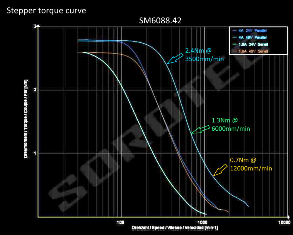
The blue arrow indicates my most-often-to-be-used feed rate for roughing in wood where there’s plenty of torque available for large depth increments. According to the green arrow, I still have nearly 50% torque available during quick smoothing or while working with soft materials like foams. I decided to stay 30% below critical speed of the machine (limited by the ball screw) for my G0 commands that won’t run under spindle load. That’s where the yellow arrow is located: Maximum velocity is 12m/min = 200mm/sec. Here, only as much as 0.7Nm are available which is 1/6 of original torque.
This way, I have good confidence to enter velocity data for the axes X and Y. For Z with half the thread height, I divided it by 2.
Axis acceleration
Imagine you want to cut a 90° corner in your program with a feed rate of 12m/min. Not unlike you when riding a bike and taking a sharp turn, the machine is not able to brake to zero on one axis in no time and accelerate on the other one simultaneously. If the axes don’t wait for each other, we’ll cut the corner round. If we do wait, the feed rate is not constant anymore - a dilemma. That’s why we need to find appropriate acceleration values.
For your bike, decelerating “appropriately” might mean to not risk wheel lock or bicycle fork fracture but on the other hand still quickly enough to not “miss” the corner. Same thing for the CNC: We don’t want it to lose steps, resonate, block, jump or twist too much while maintaining a profound operating speed, high accuracy, and low machine wear.
Sounds impossible? That’s why we will spend some more time here.
Cornering: vmax = 200mm/s, a=400mm/s^2
Take the above example: I used a pen to visualize acceleration behavior of my CNC with some conservative acceleration values. For the last path, The CNC slows down to 0 so it can take the sharp corner. All the paths before it also won’t meet the targeted 200mm/sec but the larger the radius is, the quicker the machine ran.
Motivation
“Why should Zerspanobert be accelerating quickly?” Here I have more answers. I’ll be doing a lot of short-line and 3D work. They often involve many lines of code and thus the CNC will have to change direction and feed rate all the time, maybe even use Look-Ahead Feed or G64 commands.
I do also want to keep running through material with an almost constant feed rate to not generate “hot spots” where the machine dwells before accelerating into another direction. That’s why, with at low acceleration settings, these tasks will either take long or be less accurate than I’d like them to be as look-ahead will slur trajectories.
On the other hand, high accelerations will destabilize the machine and might lead to jerky behavior - but we’ll cover that later.
Determine maximum acceleration formula
As we did for velocity calculation already, let’s juggle some formulas to get a do-not-exceed acceleration value. We need
- Newton’s second law (axial movement): \(F_{ax} = m_pa\)
- Inertia torque of the axis: \(M_a = \frac{a J}{P}\)
- Moment of inertia of the axis (cylinder): \(J = m \frac{a}{2}r^2\)
- Motor torque required for linear movement: \(M_d =\frac{F_{ax} P}{2 \pi \eta} + M_a\)
To calculate the maximum acceleration, I combined these formulas to
\[a = \frac{M_d}{\frac{m_p P}{2 \pi \eta} + \frac{J}{P}}\]In words: The acceleration the machine can theoretically reach is the available motor torque \(M_d\) divided by the portal’s mass \(m_p\), weighed with ball screw specific parameters like thread width \(P\) and the overall motion system’s efficiency \(\eta\) plus the moment of inertia \(J\) the rotating axis components have, weighed again by thread width.
Working with values
Let’s add some data - for my BasicLine 0607:
| Parameter | Symbol | Value | Unit |
|---|---|---|---|
| stepper torque @ vmax | Md | 0.5 | Nm |
| portal mass | mp | 40 | kg |
| ball screw thread width | P | 0.01 | m |
| ball screw radius | r | 0.008 | m |
| axis’ rotating mass | ma | 4 | kg |
| axis system efficiency | n | 75 | % |
Where I didn’t know the exact values, I took worst-case data. For the stepper motor, assuming maximum velocity and lower voltage is worst-case because its torque will be much lower than at standstill at no load. I just guessed my portal weight and the rotating mass of my longest axis plus stepper’s core. Typical ball screw efficiency is at 90% but I had to take both bearings and losses of the pre-stressed linear guides into account. I conservatively estimated the axis system efficiency.
Ok, here’s what those values return in the formula as a maximum acceleration for my BasicLine CNC:
\[a = 5.0m/s^2\]What this value means
Let’s see what time the machine would need to accelerate from 0 to top speed. Now good old law of uniformly accelerated motion comes in:
\[v(t) = at \Rightarrow t = \frac{v_{max}}{a} = 40ms\]How much distance do we cover to accelerate from 0 to full speed (\(s_0 = 0, v_0 = 0\))?
\[s(t) = \frac{a}{2}t^2 + v_0t + s0 \Rightarrow s(t=40ms) = 4mm\]What axial forces does the portal have to take during acceleration? \(F_{ax} = m_pa = 200N\)
The acceleration I calculated here is more than a magnitude larger than the manufacturer’s default setting 300mm/s^2. I wouldn’t have expected such a big difference.
🤔 I must have overlooked something.
Conclusion: A matter of experience
The formulas neither take machine stiffness into account nor do they show how the machine would twist or jerk under dynamic load. What is Jerk, you ask? View this short youtube video for an explanation in CNC context. I didn’t find any point in my CNC software where I could set values for allowable Jerk, though.
Although I learned a lot about how math can help guide us here, it all boils down to experience again:
- How heavy and sturdy is the machine?
- What kind of material am I working with: Is it forgiving or stiff?
- Do I have complex, possibly 3D jobs to do?
- Does my CNC live in a production environment where machine time is important?
- How does the CNC sound and feel with high acceleration values?
I entered a value of 800mm/s^2 as acceleration for the X- and Y-axes. It seemed to work without issues whatsoever. After all, it remains below the calculated motion system’s capability by factor 5.
Tryout
I know, this was a long read and much more an educated guess than conducting strict math 😅. Still, we’re now ready to home the machine the first time. Try it. After that, use the jog menu to go to Machine 0 on all axis. Does it stop before hitting the mechanical end?
Then use the continuous jog to move close to the other end of all axes. Carefully jog the last millimeters. Are measurements and settings all correct?
If so, try the 100% speed modifier key (Shift - on my keyboard). Does the CNC move rapidly and automatically stop at axis end without collision?
Congratulations!
Max motion settings calculator
You bravely read the whole article. Kudos! Be rewarded with a little Excel tool: CNC kinematics helper you can download and use to work through some numbers for your machine. Needless to say that I cannot take any responsibility for the results you get when using that tool or any harm that wrong values can do to your machine or even to your health.
Update
I played around with maximum speed and acceleration values for my machine again.
300mm/s was too quick and I would get software limit violation errors. With 240mm/s my machine would vibrate a lot. So I just gently increased maximum speed to 220mm/s which seems to be fine.
I also increased acceleration to 1200mm/s^2. The only issue with this new value is that for short movements, the machine is shaking just a bit more. When acceleration is complete, everything will calm down again. Let’s see if this affects machining quality.
Update 2
The above calculation, while not wrong mathematically, is misleading. It suggests that every axis could run with that speed which is just not the case. I have confirmed with my machine’s control software supplier that the 125kHz is the total max. command frequency of the system. If I try to squeeze in more steps, I’ll get an “Velocity was higher than max!” error.
That’s why such high velocity value should not be taken if the machines is planned to operate at full speed with all axes involved. I wrote a follow-up article and linked it here for your reference that uses values that work in any situation, even with all axes moving at full speed.