passtdas - a helper for your CNC
The Problem
A friend of mine wrote to me. He uses a CNC gantry milling machine as a hobby, just like me, and often produces unique pieces. However, the resulting leftovers are sometimes too valuable to throw away. To maximize material utilization, he tries to use these offcuts as blanks for future projects.
“Do you know how I can find out on the machine whether my milled part fits on the blank?” - Anonymous
This happens: According to the dimensions, the workpiece just fits on the blank. If you set the zero point even slightly incorrectly, the milling cutter will move beyond the workpiece boundaries, and scrap it is.
The Solution
It would be great if the machine followed the contour of the workpiece before starting the milling process, wouldn’t it? This way, you could easily find out whether the blank is actually completely within the workpiece boundaries.
Since I can’t find a quick solution online right away, I’m thinking about writing my own software to implement this. So I’m getting to work.
TODO: ADD VIDEO LINK
The Software
For a quick prototype, I choose the high-level language python. Why? I have a fairly good command of python, libraries for the necessary geometric calculations are available, and the written program can be easily compiled into an all-in-one file.
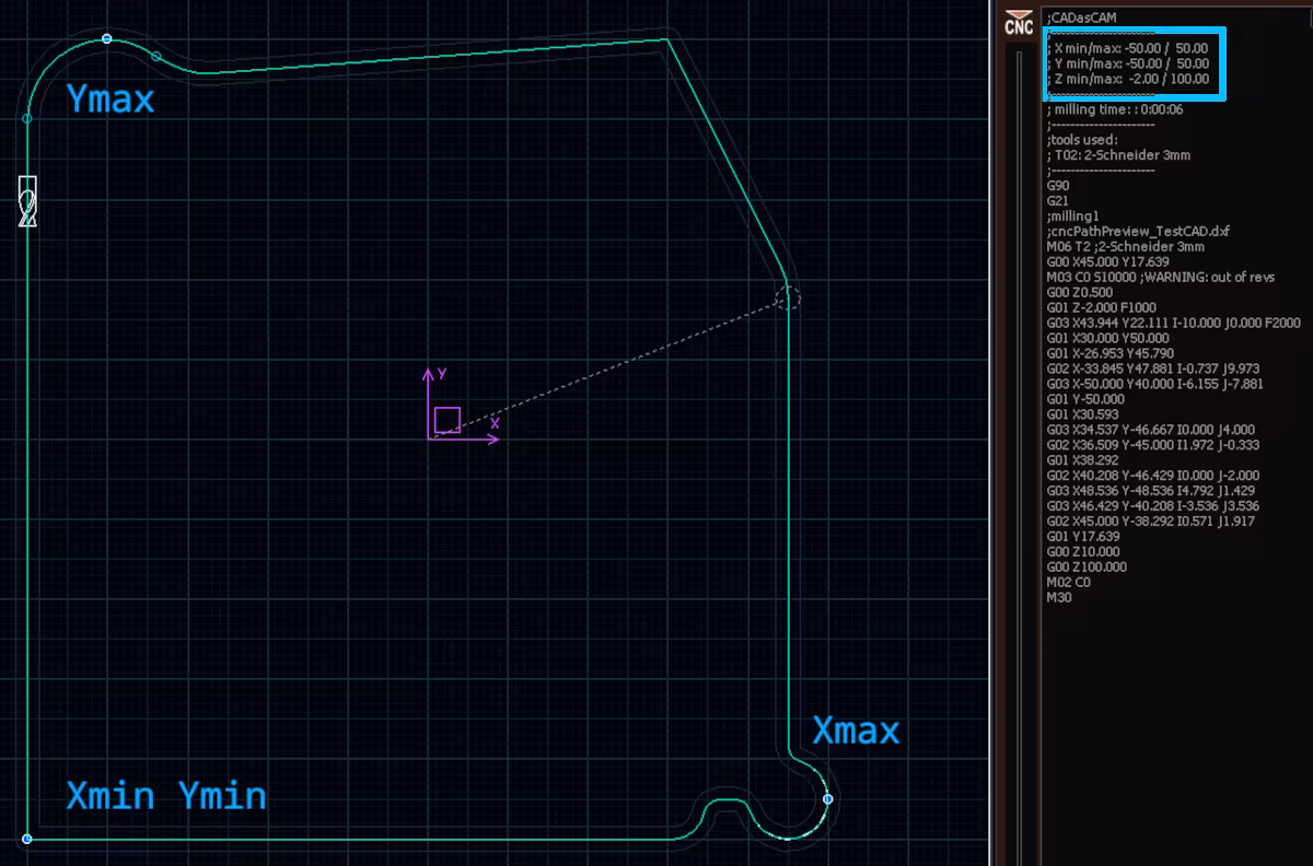
The program is designed to read machine instructions (G-code) and analyze the milling paths. The positions at which the maximum and minimum X and Y values are approached in the milling program are to be saved and output as a motion command in a path file.
If this program is loaded onto the machine, an “extreme value” determined in this way is approached and the Z-axis is lowered from the safety height to the measuring height. The program is then paused so that the operator can make adjustments to the workpiece position. Only by entering another start command will the next extreme value be reached, and so on.
This program will be called passtdas.
Program type
I’m choosing a console program with few parameters:
| Shortcut | Parameter name | Description |
|---|---|---|
-f |
--file |
The source file to be analyzed. Required. |
-s |
--zsafety |
Safety height the machine will do flyovers with. Optional. |
-p |
--zprobe |
Probe height the machine will pinpoint to. Optional. |
The two height parameters are given default values, so they don’t always have to be specified.
Input
passtdas reads files and searches them line by line for motion commands like G00, G01, G02, G03. While the analysis is simple for linear movements like G00, G01 – linear movements can be expressed using point-to-point connections whose extreme values cannot lie between the points – it can be quite challenging for circular segments.
The height information on the Z-axis is also read and saved. This allows the machining technician to quickly check whether the maximum milling depth matches the desired one.
If the G-code file contains no instructions or incorrectly formulated instructions, passtdas displays corresponding error messages and aborts the analysis.
Definition of Circular Segments
Background: Circular segments can be defined in two ways in G-code.
[...]
G00 X5.660 Y-0.000 Z10.000
G02 X-5.660 Y0.000 R5.660 F1600
[...]
Command:
“Move a circular arc clockwise from point
X5.66 Y0with radius5.66mmto pointX-5.66 Y0with feed rate1600mm/minat height10mm.”
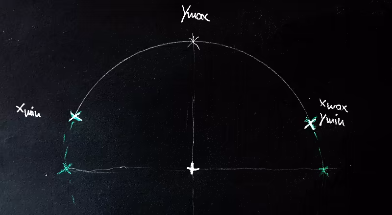
Drawing these commands creates a hanging semicircle. Circles can be defined using three points. However, only two points are given. The third point must be calculated from the specified arc radius using the start and end points.
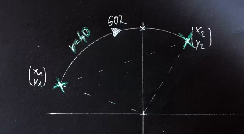
Task: Find the extreme points of this arc in the XY plane.
But an arc can also be defined like this:
[...]
G00 X-2.5696 Y5.0431
G03 X-4.6258 Y3.2616 Z-0.5000 I2.5696 J-5.0431
[...]
Command:
“Traverse a circular arc counterclockwise from point
X-2.56 Y5.04with center coordinatesI2.56 J-5.04to pointX-4.62 Y3.26.”
Drawing these commands creates a short circular segment in the upper left quadrant. Although three points (start and end points, as well as the center of the circle) are given, it can sometimes be difficult to determine whether an extreme value is being reached somewhere along the arc.
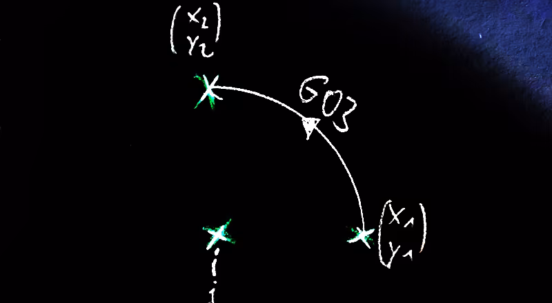
Task: Find the extreme points of this circle in the XY range.
Calculating the extreme points of circle segments
A circle segment can have up to four additional extreme points, depending on its range: X+, Y+, X-, Y-. For a full circle, these are always the coordinate intersection points as seen from the radius.
def get_extremes_from_arc(arc, coordinates):
  # [...]
    x_plus_radius = [center_x + radius, center_y, xyz[2]]
    y_plus_radius = [center_x, center_y + radius, xyz[2]]
    x_minus_radius = [center_x - radius, center_y, xyz[2]]
    y_minus_radius = [center_x, center_y - radius, xyz[2]]
    extremevalue_order = [x_plus_radius, y_plus_radius, x_minus_radius, y_minus_radius]
    if (arc[1] - arc[0]) < 0:
        # crossing the 0° line (x-axis), handle overflow with nested if below
        arc[1] += 360
    result = []
    for crossing_angle in range(0, 721, 90):
        if crossing_angle in range(int(arc[0]), int(arc[1] + 1)):
            i = int(crossing_angle / 90)
            if i > 3:
                i -= 4
            result.append(extremevalue_order[i])
  # [...]
If the circle center and radius are known, the swept angle can be determined from the start and end points. This makes it clear whether the circle’s start and/or end points themselves represent extreme values, or whether additional extreme values arise from sweeping over a coordinate origin. It is precisely what the above code example does.
Data table
All possible extreme values (two for a line, up to four for a circle segment) are now collected in a data table. Once each G-code line has been evaluated and the list is thus complete, the maximum and minimum values for each axis are determined from this list.
This ultimately creates four XYZ coordinates, which describe the maximum extent of the workpiece for each spatial direction.
At the same time, the program searches all commands to the Z-axis and remembers the maximum plunge depth.
Output
The command-line program has no visual output. Therefore, I’ll limit myself to creating a simulation program for the milling machine in which the workpiece extension is approached and paused at each point:
G90

# Go to coordinate zero
MSG "Zmin of this job: -1.0"
G00 Z40
G00 X0 Y0
G01 Z15 F1200

MSG "PathPreview: Hit START to go to Ymin: ['0.0', '-5.66']"
M00
G00 Z40
G00 X0.0 Y-5.66
G01 Z15 F1200

MSG "PathPreview: Hit START to go to Xmin: ['-5.66', '0.0']"
M00
G00 Z40
G00 X-5.66 Y0.0
G01 Z15 F1200

MSG "PathPreview: Hit START to go to Ymax: ['0.0', '5.66']"
M00
G00 Z40
G00 X0.0 Y5.66
G01 Z15 F1200

MSG "PathPreview: Hit START to go to Xmax: ['5.66', '0.0']"
M00
G00 Z40
G00 X5.66 Y0.0
G01 Z15 F1200
# [...]
The above example traverses the extreme values of a circle with r=5.66mm. It always moves to a safety height of Z40 to cover the points and, upon arrival, slowly moves the Z axis at F1200 to the target height of Z15. It is important that the zero point in Z has been correctly measured beforehand – otherwise, a collision with the workpiece may occur.
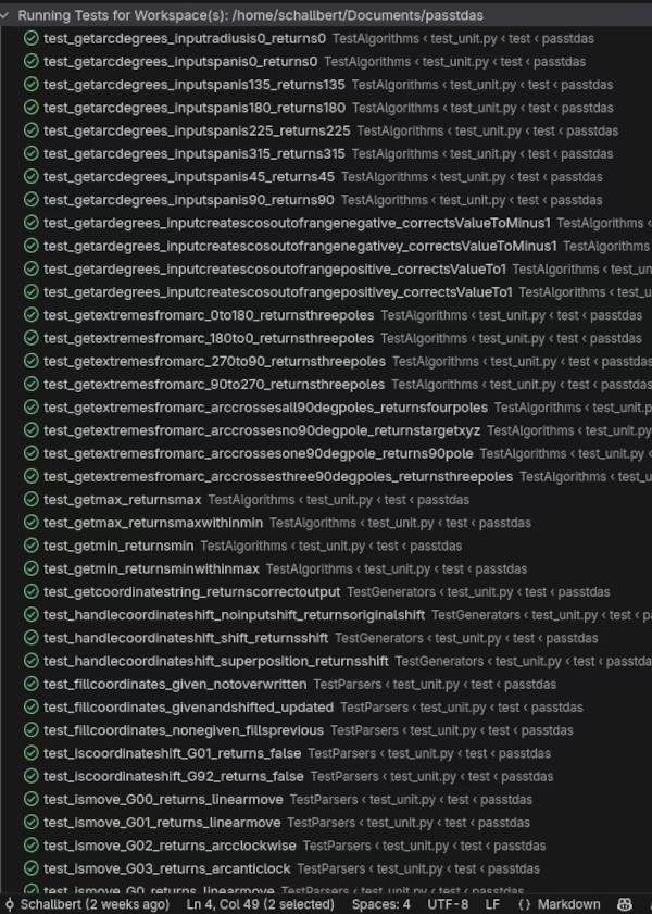
Testing and Verification
To see if the program works as expected, I created three test files:
- Unit tests: Tests individual functions in the program, e.g., whether line and circle segments are correctly recognized
- Integration tests: Tests whether functions function correctly in conjunction, e.g., the correct calculation of extreme values based on input values
- End-to-end tests: These tests check the entire function chain, e.g., whether incorrectly formatted input files are recognized
Finally, I create several test files with the program and move to the extreme values generated from them with my CNC.
Open-source software
The source code for passtdas is available for free on GitHub, but must be interpreted using Python.
I’ll build a user-friendly and easy-to-use program once enough people have expressed a desire for it.