PC-Upgrade
Project Overview
- Difficulty: Amateur 3/5
- Cost: ~€500
- Time required: ~20 hours
Goal and Motivation
In 2006, I treated myself to a gaming PC. I bought an HTPC case. It’s relatively flat and fits in the rack of a stereo system. In 2015, I replaced the components for the first time when the hardware became too slow. By the end of 2025, it was time again: The power supply was struggling with the power consumption of the new graphics card, the hard drives were filling up, and games were no longer running stable.
Upgrades
In short: New hardware is needed. However, this new hardware generates significantly more heat than the previous system. Therefore, some modifications are necessary to optimize airflow. Sounds like a great project with many facets that define this blog: mechanics, electronics, software, and CNC milling.
New Components
To be installed:
- 650W Enermax power supply replacing 400W
- New MSI B550 motherboard
- AMD Ryzen 5600X replacing Intel i5-6500
- 32GB DDR4 RAM instead of 16GB
- 1TB PCIe SSD instead of SATA SSDs
- 140mm fan in the 5.25” bay
- 2x60mm fans in the rear exhaust vents
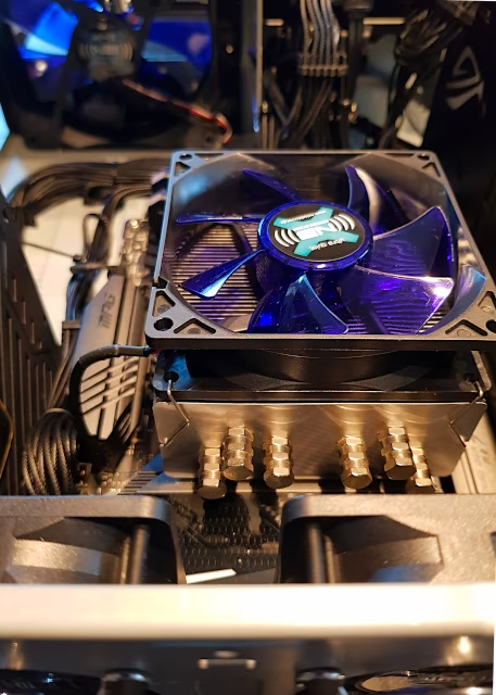
- 96mm CPU cooler with a new heatpipe cooler
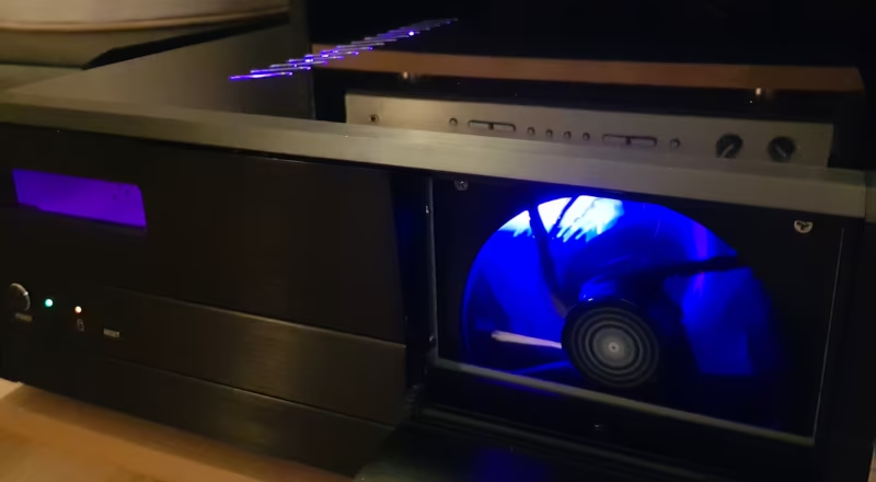
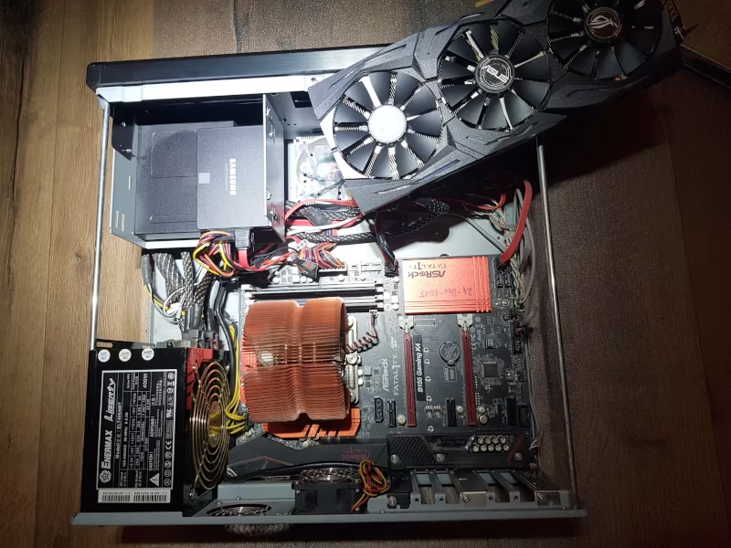
I’m getting most of the components used. Only power supply, hard drive, and fans are new. However, it quickly becomes apparent that I need to modify the case: The graphics card is so long that it collides with the 3.5” bay, where the hard drives and card reader were previously located. The large 140mm fan only fits in the space where the 5.25” drive bay is located.
Therefore, both bays must be removed or modified with an angle grinder to create space. I also need a mounting bracket for the fan in front of the 5.25” opening. A nice finishing touch for the case would be the ability to automatically control the drive bay door. Then it would only open when the fan is running under heavy load and remain closed during normal operation.
Modifying the Case Lid
In my article on milling SECC steel, I show how to add extra slots to the case lid for better ventilation of the graphics card.
3.5” Bay
 The graphics card is overlaps the 3.5” bay by 1cm. Luckily, the bay can be removed in no time. So I grab the angle grinder and cut a section out of the bracket. Then I drill a few additional holes in the sides of the bay so that my 2.5” SSDs can be mounted on the side of the bay opposite the graphics card. The bay cover also gets another hole for attaching it to the case, since two locking tabs are no longer available due to the cutout for the graphics card.
The card reader uses the full depth of the bay. I’m already worried that I won’t be able to reinstall it at all. I opened its casing as a test, and lo and behold: only the front third is actually occupied by circuit boards. The rear section appears to exist solely for mounting. So I cut off the rear part of the card reader casing and reassemble everything so that it now fits properly in the slot.
5.25” Bay
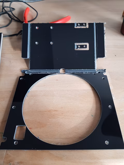
The bay is tall enough to accommodate two drives. However, I hardly ever use CDs or DVDs anymore — and when I do, an external drive suffices. So, I can remove the empty drive cage and mount a fan in its place. To do this, I’m designing an adapter bracket in CAD that includes mounting points and cutouts for the fan.
Fan Placement
 I strategically place case fans to create two separate airflows within the PC case: The CPU power supply airflow is directed to the front of the case via a 140mm fan, while the airflow to the rear of the case is directed to the CPU cooler, from where the warm air is exhausted through the power supply and two additional 60mm case fans.
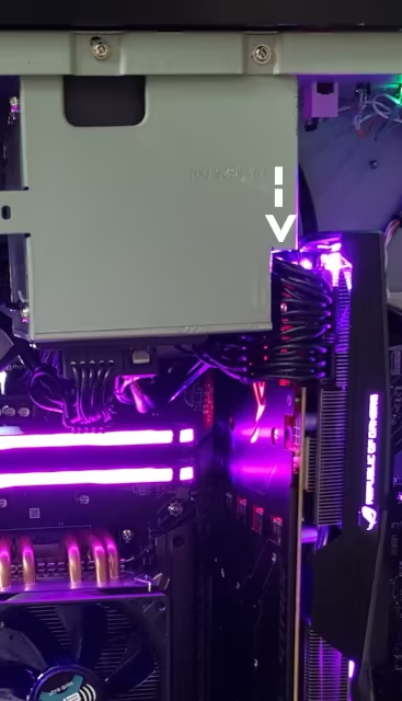
Airflow to the graphics card is assisted by a 140mm fan mounted outside the case. The graphics card itself exhausts the heated air directly through the case lid.
To connect the external fan, I cut a hole in a slot cover for PCI slots. The socket of a fan connector press-fits into this hole. I secure the socket in the cover with hot glue and connect the fan to an AUX fan header.
Front Panel Control
Now, the front panel should open automatically as soon as the fan spins. It’s more complicated than doing it manually, but this feature really makes the case interesting. So, I remove the panel lock and add a mount for a model servo to the adapter bracket, which will open and close the panel.
Electronics
The servo requires a control signal. I also want to set the flap position, like the fan, based on temperature, so I need to read the voltage applied to the fan. For this, I’m using the microcontroller ATTINY44. I’ve populated the circuit with only the bare essentials:
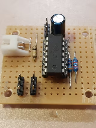 The microcontroller outputs a pulse-width modulated signal to the servo. Its power supply is buffered by an electrolytic capacitor. I’m routing the power supply for the case fan via two connector strips. There, I tap the signal using a voltage divider and feed it to an analog input. Otherwise, there’s only one additional resistor, which pulls the microcontroller’s RESET input to
 VCC, keeping it powered on.
Software Requirements
The software requirements are simple and clear:
- When the fan is off, the flap should close.
- When the fan is running, the flap should open.
- To prevent the flap from moving back and forth too frequently, the flap’s state should be changed with a slight delay and only if the fan has maintained its current state in the meantime.
The resulting software is available on my GitHub account.
Software: Main Loop
I keep things simple when controlling the model servo: I use the Arduino Servo library.
The program doesn’t do much. I initialize the servo servoHatch, which is controlled later in the program, define a few variables, and specify which pin the fan’s voltage divider is connected to. The main loop simply reads the voltage at the fan and decides, based on that, whether the flap should move.
I pass the evaluation to the flap control. The program then waits 15ms and starts again.
Servo servoHatch;       // create Servo object to control a servo
uint16_t fanVoltage{0};    // variable to read the value from the analog pin
bool open{false};

void setup() {
    pinMode(pinFanVoltage, INPUT);
}

void loop() {
    fanVoltage = analogRead(pinFanVoltage);    // reads the value of the fan voltage (value between 0 and 1023)
    open = mapHatchState(fanVoltage);


    setHatch(open);
    delay(15);                           // waits for the servo to get there
}
Software: Hysteresis
Using the mapHatchState function, I define the target state of the hatch based on the voltage at the fan.
If the voltage remains below approximately 4.8V for a sufficient duration, the hatch closes or remains closed. If it exceeds this voltage, the hatch should open. The duration of the state change depends on the voltage itself; at values far below the threshold, the aggregator fills up more quickly, and the hatch state also changes more rapidly.
bool mapHatchState(uint16_t voltage){
    #define maxint 32767 - 1024
    #define minint -32768 + 1024
    static int16_t vAggregate{0};
    static bool hatchOpen{false};

    // Divider VCC 33k T 22k GND, 12V fan will yield 4.8V at divider --> 983 digit
    // So a value of 410 is roughly 5V which allows Fan start + hatch open
    vAggregate = vAggregate + voltage - 410;
    if (vAggregate > maxint) {
        vAggregate = maxint;
        hatchOpen = true;
    }
    else if (vAggregate < minint) {
        vAggregate = minint;
        hatchOpen = false;
    }

    return hatchOpen;
}
Software: Moving the Hatch
The setHatch() function checks the desired state of the hatch and moves it accordingly if it deviates from its current state.
A target angle is specified to the servo using write(), which is then set and maintained. The movement is gradual and occurs through iterations of hatchState, as otherwise the hatch would move far too jerkily and quickly.
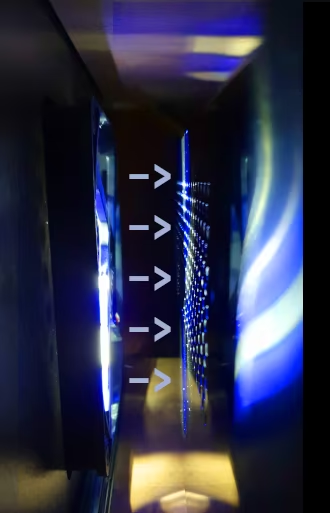
Testing the flap control by adjusting the fan’s voltage
void setHatch(bool open){
    static uint8_t hatchState{180};  // variable to capture current position, default closed
    static bool wasMoving{false};
    bool isMoving{false};

    if (open && (hatchState > 0)){
        hatchState--;
        isMoving = true;
    } else if (!open  && (hatchState < 180)) {
        hatchState++;
        isMoving = true;
    }


    if (!wasMoving && isMoving) {
        servoHatch.attach(portServo);  // connect servo on start
    }
    else if (wasMoving && !isMoving) {
        servoHatch.detach();  // disconnect servo on finish
    }

    servoHatch.write(hatchState);
    wasMoving = isMoving;
}
The attach() and detach() functions define the signal output to the servo, internally assigning the microcontroller pin to the servo exactly as it’s wired. In my experiments, I discovered that the servo consumes very little power when stationary in the detached state — much less than when it’s left attached and simply not sending any further movement signals. Therefore, I attach it for each movement and then detach it again afterward.
Result
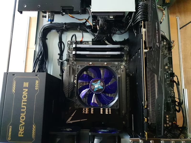
I now have a nicely organized, modern PC. Using various bloatware solutions (which I uninstall immediately after finishing the work), I manage, after some cursing, to synchronize all the LED colors. A particular highlight is the automatic flap, which activates along with the fan when the CPU load increases.