🎄 Breadboard Fireplace
Project stats
- Difficulty: beginner 1/5
- Cost: 8…25€
- Time: ~1h
Abstract
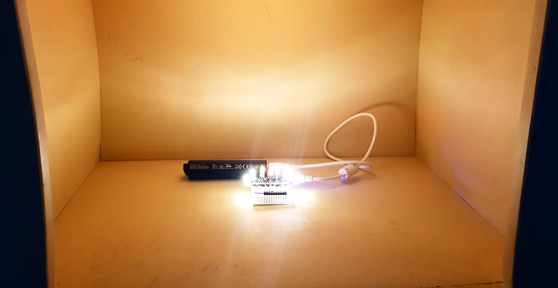
This is a quick and easy project that demonstrates how to use an embedded device and some LEDs to create a warm and comfortable living room environment. Tied to a powerbank, this little thing will glow all evening and create a warm and comfy atmosphere. I borrowed parts of the idea for this project from a book in which I read a lot when I started with embedded software design in C years ago.
Project cost varies on the components you choose. If you take an original Arduino, it will be on the upper end - but in this case you pay tribute to the hard-working developers and engineers at Arduino, creating open source solutions for all of us 🥳
The Hardware
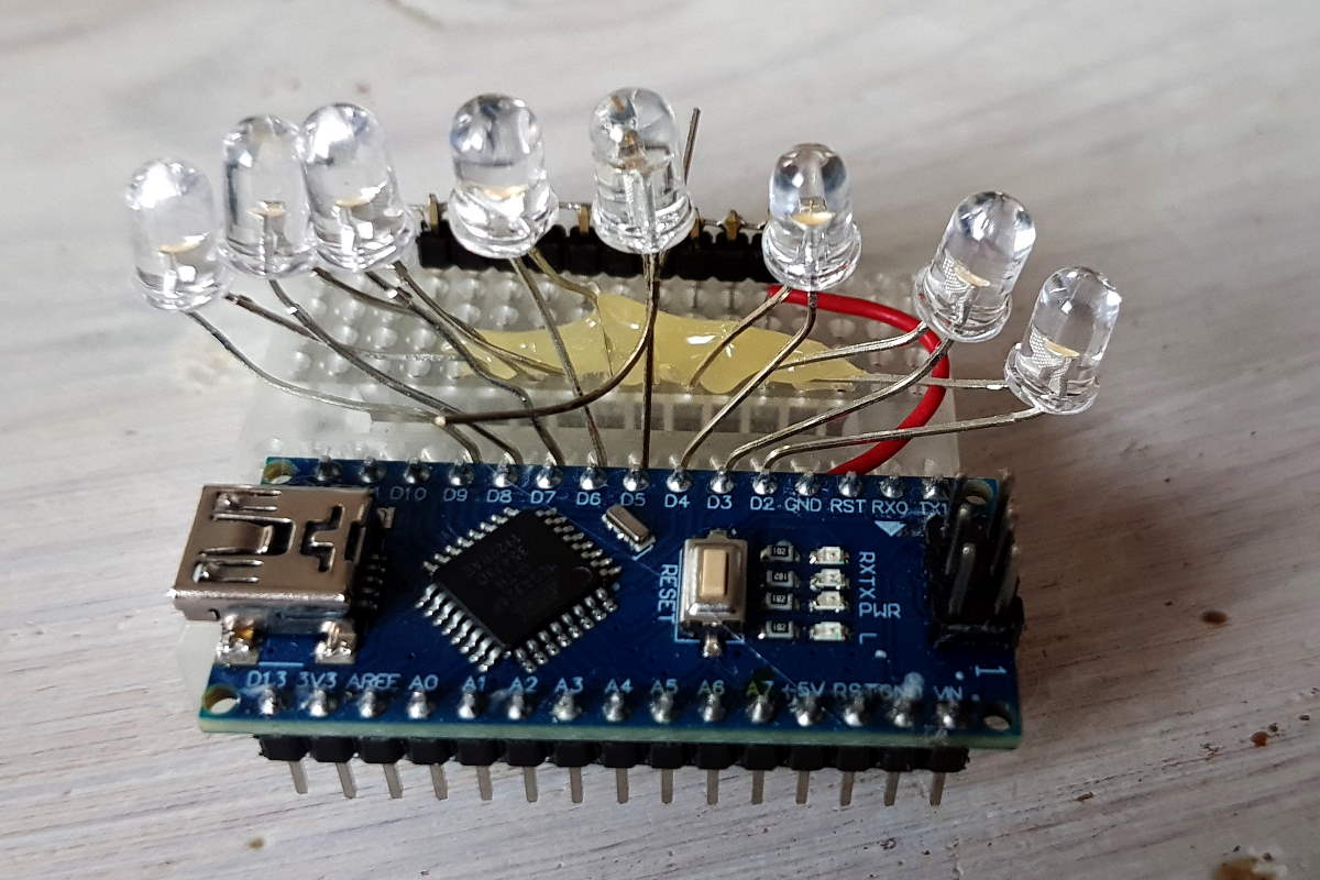
Of course, you can use any microcontroller board that supports at least 8 digital outputs and 1 analog input. In my example I’m using an Arduino Nano replica board I had flying around somewhere. Time to upgrade to the “original”… You should have a small breadboard, a couple of wires and eight LEDs at the ready. I recommend using 5 warm-white LEDs, 2 yellow LEDs, and 1 red LED with similar brightness (lumen count) to yield colors that are similar to a real fire.
The Software
The software creates a flickering lights effect with varying update speed.
Setup
On startup, in setup() I define pins the LEDs are connected to as outputs.
I make it read an open analog pin once and takes its (undefined) value as seed for the pseudo random number generator discussed later.
Loop
In the infinite loop, the program calculates a new random number and then hands this number over to the downstream functions. Here, a random number generator creates value which is then used to
- determine which of the eight LEDs should be on
- set the time for which this LED status shall be maintained.
Finally, the LEDs are set accordingly and the loop repeats at the beginning.
Linear Feedback Shift Register
The Random Number Generator is implemented as a so-called linear feedback shift register (LSFR) with a length of 32bit (repeats its pattern after max. 2^32 steps). This implementation uses the “Galois type” of LFSRs.
Galois LFSR implementation
void loop()
{
    iRandNum = (iRandNum >> 1) ^ (-(iRandNum & 1u) & 0xd0000001u);
    [...]
}
There’s a lot going on in this line of code, so please let me explain it down to the core.
Essential to this sort of random number generators is the XOR operation indicated by a ^ in the center of the code line. XOR means “eXclusive OR”, which outputs logic 1 only when logic inputs A and B are different. When A and B are both 0, or both 1, this gate will output 0.
Example binary XOR:
    A             B        Out
0b00001111 ^ 0b00110011 = 00111100
Left to the XOR operator, the current randum number is shifted to the right (>>) by 1. All of its contents is made less significant by one bit. In numerical terms it means that a value is integer-divided by two.
Example binary SHIFT:
    A         B     Out        numerical:
0b00001111 >> 1 = 0b00000111   15 >> 1 = 7
OK, let’s further analyze the above code line.
Right to the XOR operator, there’s another operation taking place: A logic AND (&) between our current random number and 1u which means “unsigned 1”. What it does is masking all higher bits of the randum number generator, the result of this action is a simple 0 in case the number has a 0 as its least significant bit and vice versa.
Example binary AND:
    A        B     Out
0b00001111 & 1 = 0b00000001
The negation at the beginning of this term means that, when the result of the before & was 0, the whole term will be 0b00000000... again. If it’s -1, the 2’s complement binary code will instead look like this: 0b1111111....
This is an easy way to apply a single boolean value to any longer data type without branching logic like using an if() clause.
And finally, there’s another logic AND between this term and a fixed bitmask 0xd0000001u. The latter are the “taps” of the LFSR, i.e. which bits of the current value are fed back into the system. Unravelling this hex value to boolean shows: 0xd = 0b1101 so the bits 32, 31, 29, and 1 are &‘ed with the current random number, leaving only their values untouched while all others are set to 0.
Galois LFSR Summary
Whew, that was a lot. It’s time for a couple of minutes break. Then please read the summary below for the beloved code line
iRandNum = (iRandNum >> 1) ^ (-(iRandNum & 1u) & 0xd0000001u);
Meaning: “If the least significant bit of the current random number is zero, then just shift the random number to the right. Else, in addition XOR with the tapped bits of the current random number.”
LFSRs are widely used in wireless communication technology, they are interesting for checksum calculations, cryptographers and can even be useful when programming games, e.g. for procedural map generation. LFSRs are easy to implement (as you can see they even may only use a single line fo code!) and don’t use many resources. Here’s an excellent blog post dealing with LFSRs in depth if you’re more the visual type (and less the logic one).
On the down side, their “quality of randomness” is bad because they are deterministic.
All in all I found it a very interesting topic which is why I decided to manually implement an LFSR here instead of using Arduino’s stock random() function.

Possible issue
Well, if you fully understood the code line, you see what happens if the random number contains only 0s.
It will never get out of this state again 💀
That’s why you should never initialize this type of LFSR with 0.
Driving the LEDs
The rest of the software has much more lines, but also does much more boring stuff. It takes the generated 32-bit random value and runs it past the 8 LED outputs, i.e. every LED “sees” each bit of the value. Between each of these iterations, a randomized delay is used so the flickering speed is limited to a change rate we still can perceive.
The Hardware
 Thankfully, the hardware is more easy to explain than the software:
- An Arduino Nano board is connected to a prototyping board.
- Eight LED’s anodes
(+)are connected to the digital outputsD2...D9. - Their cathodes are bridged with jumpers and connected to the Arduino’s
GND.
This is the simplest design I could think of to do the job.
Improvements
- Each LED should get a series resistor.
- In my design, the current is only limited by the maximum current the Arduino Pin is able to drive.
- Either the LED can handle well above
40mApeak current or it will inevitably break down at some point in time. - Resistor calculation should happen with the LED datasheet in mind as different LED colours have different voltages.
- Example resistor calculation
@5Vsupply: Warm-White LED:20mA @ 3.1V --> R = U/I = (Usup-Uled) / I = 1.9 / 0.02 = 95Ohm. Take100Ohm.
- Each LED could get a parallel capacitor.
- This would smooth the flickering effect.
- I could take videos in which the camera wasn’t irritated by LED flickering. That would be nice.
- Example Capacitor calculation: Average current when switched “off”
20mA, allowed voltage drop0.6Vwithin1ms. Proposed Capacitance is then20mA * 1ms / 0.6V = 33uF
You want a DIY replica?
Here you go! Breadboard Fireplace DIY instructions
