CNC Part2 - Electronics
Portal machine electronics
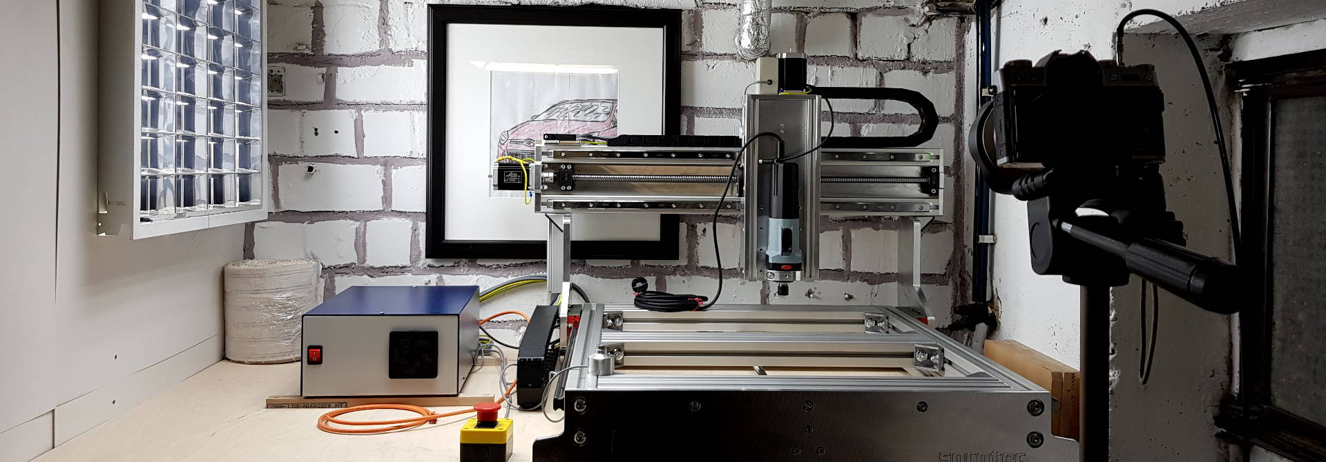
This is the second part of my Portal Milling Machine sequel. It is all about the electronics needed to control a CNC machine’s movement.
AC / Mains components
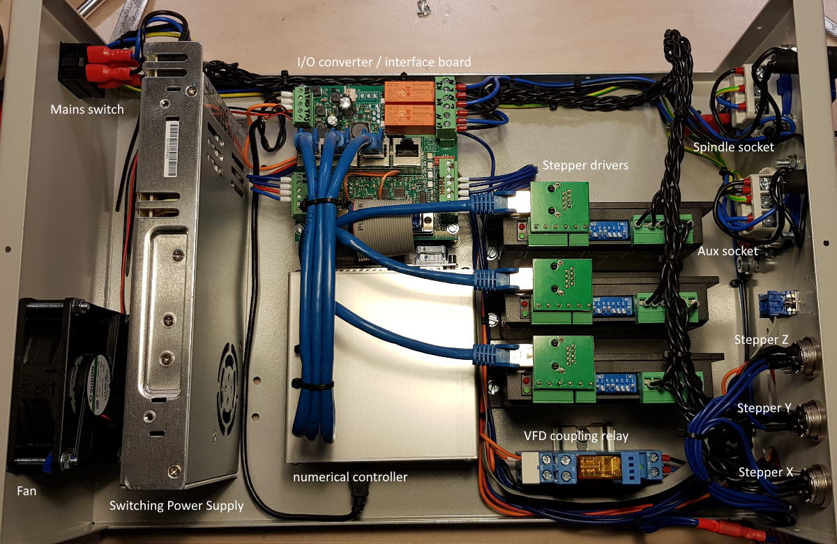
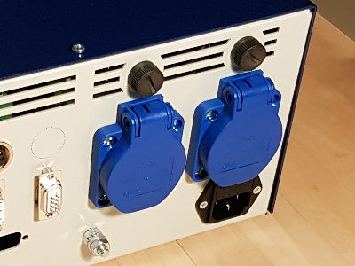
First, it houses main fuses for the whole machine control and a central power switch. It may contain mains-connected relays to control loads like spindles, cooling, dust collection. For these circuits, sub-fused power paths and outlet sockets might be available.
 Second, it has a power supply unit for the low voltage DC rail. Its voltage and power output will depend on your stepper motor load, control/breakout board voltage requirements, auxiliary low-voltage circuits it has to drive, and the region you’re living in because standards and regulations tend to differ.
Third, it may have additional signal relays to pair a variable frequency drive or similar.
Variable Frequency Drive
A VFD is commonly known as a device that controls a 3-phase alternating current machine’s speed of rotation. Supplied with 1-phase or 3-phase AC, it buffers energy in a DC intermediate circuit from where it is then forwarded to a 3-phase H-Bridge that creates a 3-phase AC output with variable voltage and frequency.
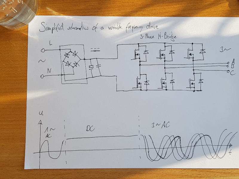 As this 3-phase AC voltage is generated by transistors in switching mode which enormously decreases transformation losses in comparison to linear operation. The output voltage is quantified in time and magnitude though (“digital”), causing undesired circuit feedback and line noise both on the in- and output of the VFD.
Almost all professional CNC spindles are 3-phase AC asynchronous machines connected to a VFD.
VFDs often have a standardized 0…10V analog input to control machine speed, enable inputs that are fed e.g. by a signal relay of the numerical control’s interface board, and an emergency halt or error signal output to the CNC interface.
As of now (2022-Feb), I don’t own a VFD. So I don’t know any details about tuning, parameter setting, and customization for a certain spindle to write about.
ELV / DC components
The typical “small” CNC’s stepper motors are driven in the PELV range (Protected Extra Low Voltage) with direct current (DC) and below 60V so no additional touch protection is needed. The “P” in PELV stands for “protected” which means that the devices are connected to grounding wires. This way, a short to ground will safely turn the circuits off, blowing the fuses.
The stepper motor drivers, one each per axis, are also placed within the box. They are typically SELV (Safety Extra Low Voltage) so that they don’t need an extra grounding.
Then there’s a signal board, breakout board, or relay board that forwards stepper signal trains to the drivers, controls auxiliary relays, reads reference switch and emergency stop inputs, and output signals for spindle, cooling, dust collection, and/or auxiliary controls.
A fan keeps temperatures within the switch box low. Maybe there also is an interface board mounted in the switch box that is controlled directly via the CNC software, e.g. through USB or ethernet. It translates and routes information to the CNC’s individual components and back to the program, e.g. for reference switches or emergency stop.
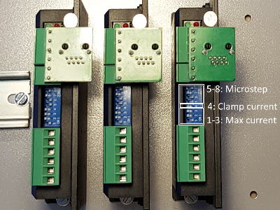
Stepper motor drivers in detail
The stepper driver interface is quite simple. It takes TTL level of 0V (low) and 5V (high) and is defined by only three inputs:
| Signal name | Description |
|---|---|
| Enable (EN) | Enables power to the drives. E.g. allows active position hold |
| Direction (DIR) | Select direction of motor rotation |
| Pulse (PUL) | Makes the motor turn a (micro)step |
Interestingly, the same three input signals are needed to control a floppy disk drive’s reading head. I did this in one of my earlier projects, a floppy-bass-organ based on the software project moppy.
 Internally, the driver interprets input signals and outputs higher voltage, high current pulses that are suited to drive the stepper motor. Two H-bridge channels - circuits with four switching transistors to control direction and magnitude of current flow through the motor’s coils - called
 A and B provide energy to the pole pairs of the stepper motor.
You can find more detailed information on stepper motor drives, microstepping, and other aspects e.g. here or on this blog (in German language).
Stepper motors
Stepper motors - like 3-phase AC or brushless DC motors - are electronically commutated. So direction and magnitude of current pulses have to be provided to the motor to make it turn continually. Most stepper motors nowadays are hybrid motors that combine a multi-toothed rotor, split into two halves that are shifted to each other by half a tooth, each controlled by one coil path.
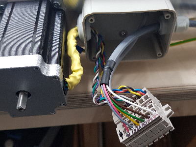
This kind of motor has four wires at least, two for coil A and two for coil B.
Unifilar hybrid motors even have eight leads that again split the coils into two parts - this way, they can be connected in series, in parallel, and also unipolar so each of the four coils can be controlled individually.
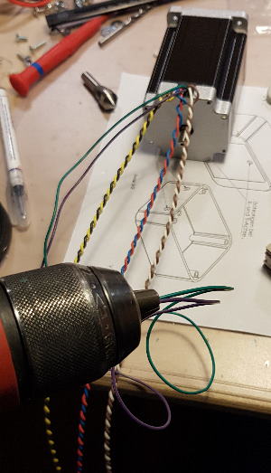 The most common way to connect a stepper motor to a CNC stepper driver is the “bipolar parallel circuit”: Here, the two coils of a pole pair are connected in parallel with the same orientation. The two wires from this parallel circuit are then connected to the driver’s
 A+ and A- outputs. This wiring is repeated for channel B.
I twisted the wire pairs that belong together with a power drill because I was too lazy to do this manually.
Unlike 3-phase AC or brushless DC machines, priority for stepper motor design does not lie on highest possible energy efficiency, low noise emissions, high rotation speed or thermal management for continuous operation, but on torque for low speeds, high clamping forces to securely hold a position, and smooth operation at low speeds. Stepper motors are built for high acceleration and shall always follow the speed of pulses as the machine’s positioning depends on that.
 Unlike servo motors, where a closed-loop control guarantees exact positioning by measuring the shaft’s position, the stepper motor’s position is assumed. The steps are counted and multiplied with the known angle the motor turns per step. This works very well as long as the motor’s maximum load is not exceeded in which case steps are lost, creating position errors.
The build
Switchbox build in 9 seconds
The build of the switch-box and wiring assembly kit that I bought took just about 8h of my time. It proved crucial to thoroughly read and understand all of the circuit plans and step-by-step instructions provided in advance to avoid mistakes that could otherwise cost hours to fix.
About the kit I like that the components are electrically matched and all necessary wires, sockets (apart from an ethernet socket), and the documentations were complete. I only missed cable straps and some lugs to simplify cable management and connections to the housing. The housing is very robust and all sockets fit in their places nicely.
Most painful when building where the solder joints of the stepper motor/D-sub connectors and their insulation. It was also not very easy to mount the numerical controller board in the switchbox.
I was really excited when I first turned the switchbox on. Was I relieved when the fan started working and all sorts of LEDs lit up to indicate a working system.
Switchbox dry run: Checking emergency off
Safety notice
No, an opened mains powered device shouldn’t be turned on unless you know what you’re doing. Yes, I have a residual current device installed in my tech shack to protect myself from hazardous voltages, and yes, I had all fuses double-checked, did quite some visual inspection and performed continuity measurements on every single connection to exclude miswirings. Luckily, the control box passed the initial function test. Both the emergency signal state was correctly interpreted and also the CNC board’s LED flashed with the expected 1Hz rate.
Building a “Mini Control / Series C1”
For the Maker Faire Ruhr 2024, where I was one of the exhibitors, I built another machine control box: The simpler “Mini Control / Series C1”. I have embedded a time-lapse video of it here:
CNC electronics assembly
Advantages:
- Quick assembly
- No soldering
- Many snap-in parts
- Small housing
Disadvantages:
- Connection to the machine is via screw terminals; Separation from the machine not possible
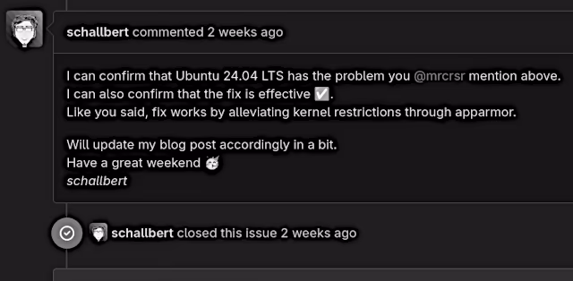
- Loud fan, active even when idling (but can be solved with “Schallbert’s Fanhack”)
- Several external power supplies (stepper motor supply, 24V supply, spindle switch box)
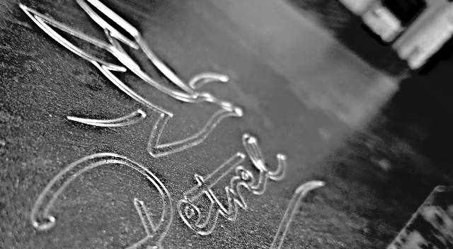
I did a lot with the associated small CNC milling machine: Tuning for shorter production times, a specialization for engravings and various projects such as stamps, dithered images and multi-colored carves.