CNC Tuning #2
This is the second part of my series on optimising production time on CNC milling machines. It focuses on the kinematic machine parameters for engraving operations.
Step 2: Tuning the kinematic parameters of the portal milling machine
I have explained the theoretical basics in detail in the article on CNC control configuration. After many tests and consultation with the manufacturer, I recorded my problems with it and the associated solutions in Conclusion on one year of CNC operation. The following sections apply the above findings to a demonstration machine that I was able to borrow.
Travelling speed in rapid traverse
For the demo machine, I was able to increase the rapid traverse speed from the suggested Fxy = 4m/min and Fz = 2.4m/min to Fxy = 12m/min and Fz = 4.8m/min. If I set all three axes in motion simultaneously, I get a combined step frequency of 96kHz due to the pitch of the ball screws and the microstep configuration (8 per full step) of the motors, which is below the maximum step frequency of 125kHz of the controller.
Acceleration in rapid traverse
The manufacturer’s specifications recommend aXY = 300mm/s² and aZ = 200mm/s².
I increased the acceleration in several steps and ended up with aXY = 1000mm/s² and aZ = 400mm/s² in a first round. In my experience, these values are easily possible for this small and light machine with a travel of only 30x45x14cm for normal operation. They greatly increase the production speed, because every change of direction, including those in the material grip at G01, G02, G03, are now carried out faster by a factor of 3 / 2.5.
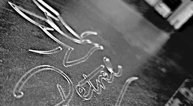
I have often operated the machine this way and I have also driven stably and safely with these values at the maker faire. The following video shows the milling machine engraving the letter “e” with values specified above.
TunedEngraving: Teaser
After that, however, I wanted to know how far I could take it. True to the motto described above
“If you don’t cross the line, you don’t know where it is”
I first tested what massive step losses sound like on this machine. So I blocked one axis with a wooden beam and carefully ran into it:
Massive step loss soundcheck
The clearly audible chattering occurs when the motor starts up, but several full steps are lost at target speed. If the rotor is already “lost” when the motor starts up, the motor only chirps without setting the axis in motion at all. If the motor only loses a few steps, but is at target speed, there is a rough and scratchy sound.
I chose the X-axis for the experiment because it is the easiest to lock. I also blocked it in the X+ direction. Reason: this machine does not have a professional fixed bearing to absorb the compressive and tensile forces of the ball screw. Instead, compressive forces in the direction of the stepper motor are safely absorbed by a flange mounted on the spindle, which presses against ball bearings located in the portal cheek.
Tensile forces, on the other hand, are mainly absorbed by the motor bearings - I didn’t want to take any risks here. So now the noise caused by sudden and jerky step loss is known - overclocking can begin!
My approach:
- double the acceleration of one axis of the machine
- jog around the axis in question, listening for strange noises and observing the axis movement
- repeat the previous steps until massive step losses occur
- reduce acceleration to the average value between “works” and “does not work”
- repeat the previous step until the machine runs smoothly
- perform all steps for the other axes as well
This is how I ended up with aXY = 4000mm/s², aZ = 1600mm/s², which is unbelievable for such a hobby machine. This is now an order of magnitude higher than the recommended values.
The small milling machine also seems to run stably here and the engravings produced look good. However, I could not imagine that I was still operating the stepper motors, driver stages and power supply unit within their specifications. That’s why I took measurements.
Electrical measurements
The power supply unit is specified with 3.7A at 36V. I must therefore not exceed this value permanently, neither in rapid traverse G00 nor in material engagement. As explained above, the rapid traverse in engraving mode is decisive due to the lower milling forces, so I have to pay particular attention to the simultaneous movement of several axes.
The motors can each handle a continuous current of 3.0A, so they don’t limit me here. In the electrical tests, I only check whether the energy consumption of the system remains within limits.
Test setup
I connect the multimeter known from this article directly to the output of the power supply unit and record voltage and current. For the experiment, I simulate the production of the engraving linked in the video above and in two runs first carry out a temporally coarse-resolution power factor analysis (2Hz), followed by a fine-resolution current determination with 20kHz.
Results
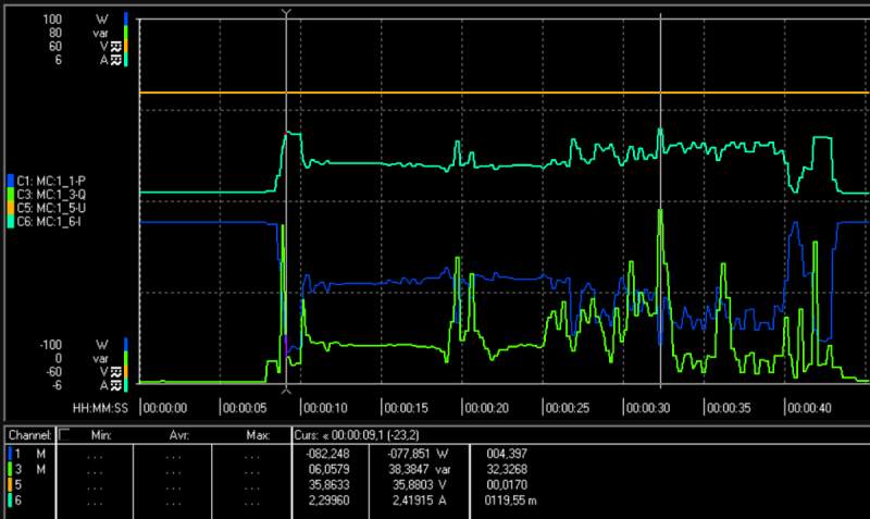
The figure above shows voltage, current, effective and reactive power. It can be seen that the reactive power (green) always shows short peaks when several axles accelerate into rapid traverse at the same time. The power consumption of an axis in G01/G02/G03, blue is on average around 45W, similar to that of constant speed in rapid traverse.
The power supply unit is able to keep the voltage orange fairly constant and even under full load only drops by just under 0.2V. Only the current value looked a little too smooth to me. At this point I suspected that the time resolution was too low and decided to repeat the experiment focussing on the current.
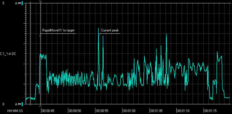
And indeed. The higher temporal resolution shows that the current consumption during acceleration of several axes shows peaks that are higher than the values already known.
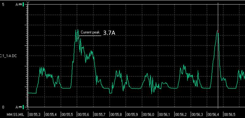
Movements on the Y-axis, which must set the entire portal in motion, are creating current spikes, especially when the other axes are still moving or have just stopped. This is related to the stepper motor drivers. They continue to brake the motors at full power for about 0.5s after stopping. The resulting overlay makes the tips look even more dramatic.
Peak load benchmark
 Well then let’s take it to the extreme with an acceleration benchmark. Will the power supply be able to maintain the output voltage even under full load while accelerating all motors at the same time?
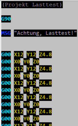
To test this, I wrote G-code that makes all axes simultaneously accelerate to maximum speed and then decelerate to zero again. Then it will return to the starting point under the same conditions and repeat the whole thing.
In this way I can find out whether the power supply has enough reserves to handle load peaks and at the same time see whether the motors are already losing steps to a large extent. On average, the applied power is 95W and the supply voltage drops by 0.28V to 35.72V. The power supply must deliver a peak of 5.14A, which is almost 40% above the rated current.
Benchmark
If you listen closely, the machine sounds a bit rough right at the start of the benchmark, but then it settles down. Lost steps can sound like this too. It is therefore very important to monitor the machine with all your senses.
Mechanical testing
Now for the final test: During the rapid traverse benchmark, I put additional load on the axes by pulling on the respective axis with my arm while the program is running. The Z and X axes continue to run stably. However, with the portal axis Y I notice that the machine now sounds different. Somehow rough, as if you were lightly dragging a rasp over a wooden board.

If I apply a large load, the stepper motor on this axis no longer even starts, but just chirps. It can no longer follow the pulses of the power amplifier. So I now reduce the acceleration step by step until the motor can accelerate the portal axis repeatably and without audible step losses, even under medium load. Here I end up with a still fast [aX = 4000mm/s² aY = 3200mm/s² aZ = 1600mm/s²].
In a final step, after repeating the benchmark five times, I carry out another reference run and look at the control software logs. All axes are now unobtrusive in terms of step losses.

Appeals for CNC tuning
Please be careful when tuning your machine. Get it to know properly before you start. Listen carefully and optimize axis by axis one after the other. Take time for tests, verifications and experiments.
Even if you have a portal milling machine that is very similar to mine, other dimensions make a huge difference in terms of stiffness and therefore possible travel speed and acceleration. Even the state of maintenance, smoother shafts, different guides, etc. can mean that you end up running different values than me.
No professional equipment is required to explore the limits of the machine. Not even a dial gauge, since step losses can also be determined with sufficient precision using the reference switches.
All I found from the electrical measurements above is that the manufacturer did a good job designing the machine and no component is undersized. On the contrary, this machine is ideal for overclocking.
And now on to the last Part 3: Optimize the path interpreter.