Automate tool length measurement
 I keep receiving questions about my post on CNC macros. In this article, I’d like to provide some answers and share details on measuring and compensating for different tool lengths.
Question: How does the macro calculate the tool length?
In the section Measuring Tool Length, the following code appears:
1 G53 G00 Z[zSafety] ;                         # Go to safety height (machine coordinates)
2 G53 G00 X[xPosTls] Y[xPosTls] ;              # Go to tool length sensor
3 G53 G00 Z[zSpindleTip + toolLengthEst + 10] ;# Move Z down to 10mm above estimated tool tip
If Z=0 is the highest position in the machine coordinate system (move with G53), are zSpindleTip and toolLengthEst negative values?
Answer:
- This line moves the machine to the value stored in variable #4506. For me, it is
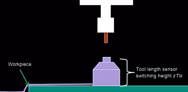
0, i.e. maximum Z height. This value is permanently stored (see here) and must be set beforehand in the macro setup dialogue. - Executes a movement to the tool length sensor (WZLS) in the machine coordinate system. To do this, I have positioned my sensor at a fixed point on the machine.
zSpindleTip(variable#4509) refers to the height on theZ-axisat which the spindle nose clears the tool length sensor. This value is negative. Why? The maximum value of the Z-axis iszerowhen it is at the very top of the machine’s travel. If you lower the axis from this point to the tool length sensor (WZLS), you are moving it in the negative Z-direction. If you add the estimated tool lengthtoolLengthEstand a safety margin of10mm(in case you made a mistake in the tool length estimation), but remain below the mechanical stop of the Z-axis, the value is still negative. However, the spindle nose now has sufficient clearance to the tool tip, because the virtual tool and safety margin have now been added.
Pro tip: In the ‘Variables’ tab of EdingCNC, you can view the values of a variable bank. Enter a bank, e.g.
#4500, and you will see the live values of all ten variables.
To understand this properly, it is a good idea to run the CNC software in simulation mode alongside the main process for testing purposes. Concrete example:
zSafety = 0          ;# machine coordinates, Z-axis at top notch
zSpindleTip = -86.43 ;# machine coordinates, where empty spindle collet touches TLS
toolLengthEst = 35   ;# the length the tool is protruding from spindle collet

G53 G00 Z[-86.43 + 35 +10] # = -41.32mm, so below max Z height
I have stored the variable names in my macro repository on GitHub.
Question: How do I calculate the workpiece height after a tool measurement?
The following scenario: You measure the tool and then determine the workpiece height using a macro. If you now change the tool length without calling the tool change macro, the workpiece zero point is no longer correct. With a shorter tool, the zero point is ‘too low’; with a longer one, it is ‘too high’.
How can this problem be solved?
Answer: Several solutions
In my view, there are three solutions to the problem.
- Always run the tool length change via the tool change macro. You can simply re-enter the same tool number there.
- Reset the Z0 point via workpiece measurement (not recommended1)
- Without a macro: Use the
G92command to shift the Z coordinate system. Example follows.

Solution #3: Shift the coordinate system
 You can shift the workpiece coordinate system using the command
 G92 Coordinate System Offset. When executed, the number passed for the selected axis is adopted as the new value in the workpiece coordinate system.
In this case, we only want to shift the relative position and thus compensate for the difference in tool lengths.
Let’s assume that the old tool T17 has a free length of 32mm and the new tool (again T17, as in this example we are simply changing tools or using a finishing tool with the same cutting data) has a free length of 24mm. The new value is shorter, and therefore the zero point must be moved down by 8mm. ‘Downwards’ is a negative value on the Z-axis in the coordinate system.
;# Pseudocode
;# (each CamelCaseWord represents a variable ID like #5003):
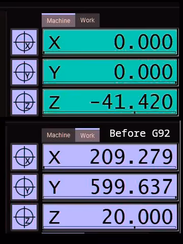
G92 Z[CurrentPositionZ + (OldToolLength - NewToolLength)]
;# 20mm + (32mm - 24mm ) = 20mm + 8mm = 28mm
Offset of workpiece zero vs. workpiece coordinate system
This calculation may seem confusing at first, as it shifts the coordinate system upwards. But this is precisely what is required to maintain the workpiece zero point relative to the tool tip: the tool is 8mm shorter. Since we do not shift the workpiece zero point downwards, the coordinate system must be shifted upwards. This compensates for the now longer distance between the tool tip and the workpiece.
| Coordinate System | Tool tip position Z [mm] | Workpiece position Z [mm] | Tool top position Z [mm] | Workpiece position Z [mm] |
|---|---|---|---|---|
| Before shift | Before shift | After shift | After shift | |
| Workpiece | 20 | 0 | 28 | 0 |
| Machine | -41.42 | -61,42 | -41.42 | -69,42 |
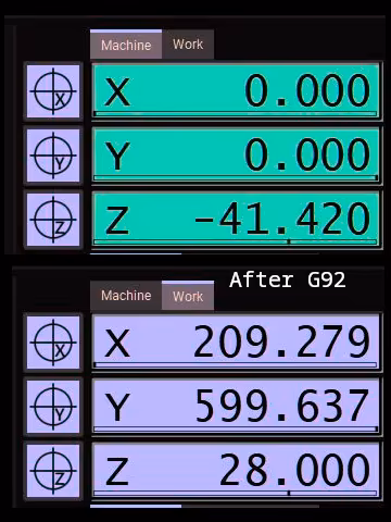 Note that shifting the coordinate system changes the position of the tool tip in the workpiece coordinate system without the Z-axis actually moving. The machine coordinate system remains unaffected by this change. However, as the Z-axis now has to travel a greater distance to reach the workpiece, its position in the machine coordinate system is lower by
 -8mm.
Prerequisites
The macros only work under certain conditions:
- The tool length has been measured beforehand, or tool changes are always performed through the macro.
- The workpiece zero point has been determined with known tool length.
- There hasn’t been any emergency stop or other critical error in between. This would clear the volatile memory for the relevant variables.
-
In my view, re-measuring the workpiece height in the Z-axis after a tool change adjusts the wrong parameter. In reality, it is not the height of the workpiece that has changed, but the position of the tool tip. I would therefore always prefer to adjust the parameter that has actually changed. ↩