Engrave Stainless Steel A2 / AISI304
Why this attempt?
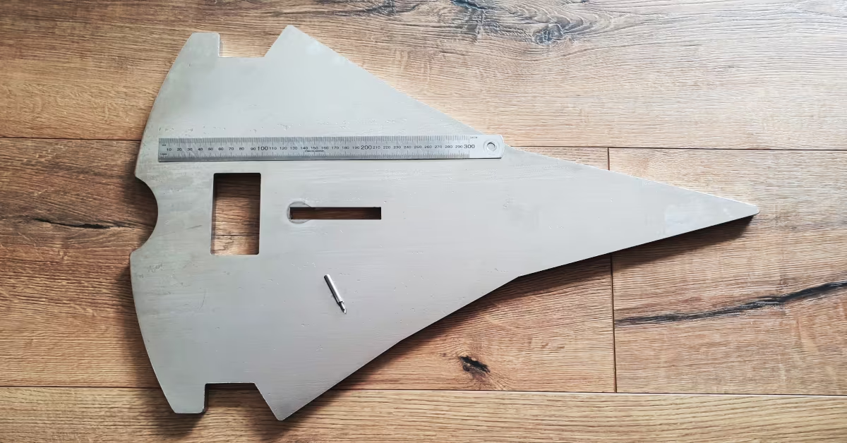
I was asked if I could engrave an auxiliary anchor for a sailing yacht. This anchor is made of 10mm thick stainless steel sheet and, with dimensions of 389x630mm, fits my engraving machine.
I’ve never worked with this material before and was so curious that I accepted the job.
The Material
The anchor is made of AISI 304 stainless steel. Other names for this alloy are ‘18/10’, ‘18/8’ (referring to its chromium/nickel content), or ‘V2A/A2’ (referring to its development from experimental melts or its production process, specifically being “Air-hardened” or by alloy group). It is relatively malleable and therefore frequently used in industrial applications.
However, this stainless steel has a few disadvantages for machining: Its thermal conductivity is quite low. Therefore, little heat is transferred to the material, which causes the milling cutter to get pretty hot. Additionally, the material is tough. The chip doesn’t detach well from the tool, easily creating built-up edges. This results in imperfections in the milling path. If the cutter pushes chips ahead of it, the material isn’t completely cut, and burrs tend to form. Furthermore, stainless steel is work-hardening: if the cutter rubs or dwells on the material, the pressure it exerts alters the material surface, making it harder than the tool itself.
All these properties combined lead to high tool wear and a tight requirements on cooling. The cutting parameters must also be kept in a narrow range.
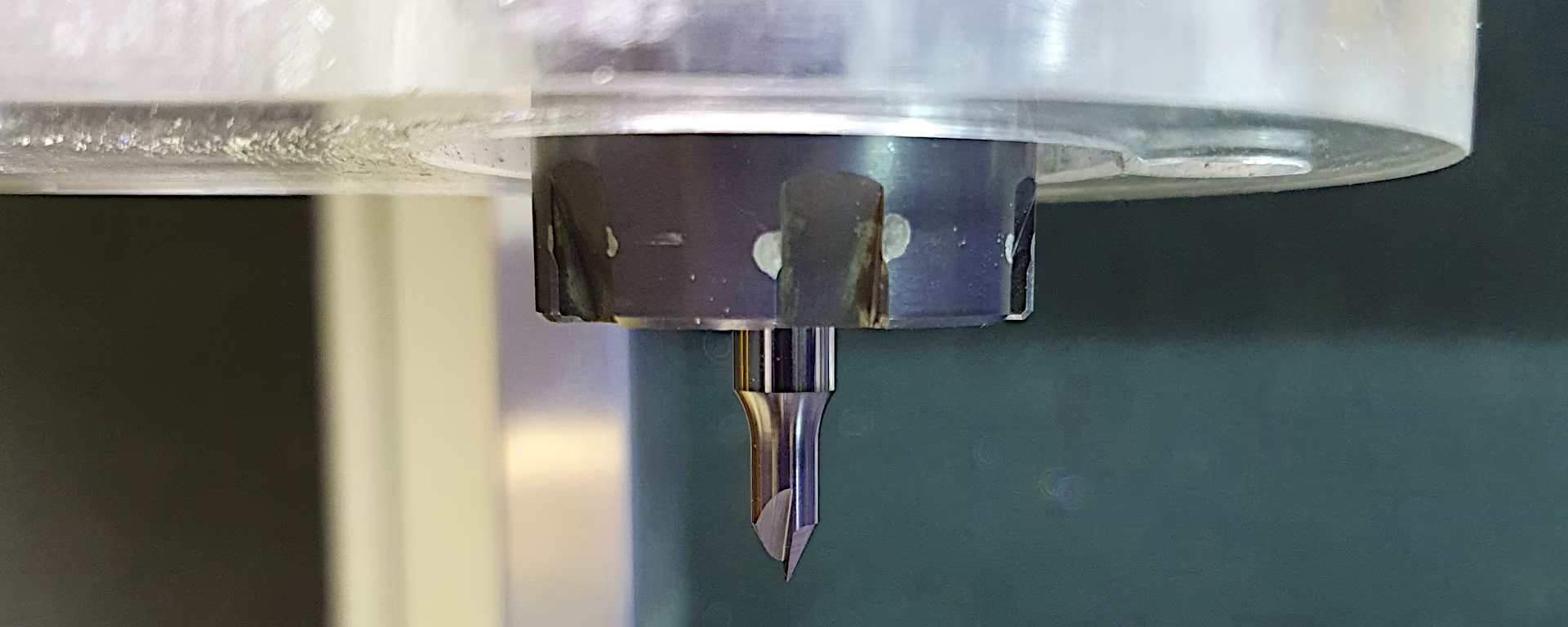
The Tool
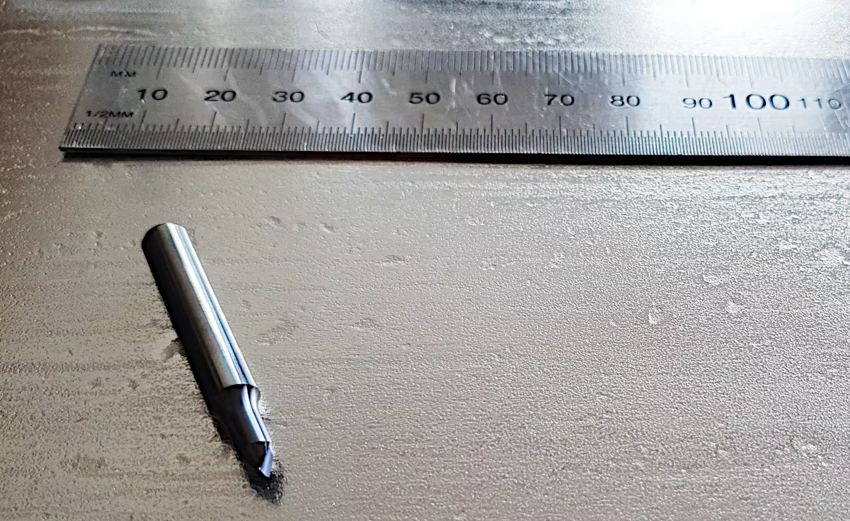
I’m choosing an engraving cutter from vhf specifically designed for machining stainless steel. With a 6mm shank diameter, but only a 4mm cutting diameter, a short straight cutting edge, a 60° engraving angle, and a 0.4mm tip diameter, the tool appears compact and sturdy. The cutter is coated with an AlTiN coating.
Will the thin tip withstand the milling forces and heat generated?
Discussion about milling parameters
In the forum cnczone.nl I’m asking for recommendations on depth of cut, feed rate, and spindle speed for my solid carbide end mill.
My internet research1 suggests a target cutting speed for AISI 304 of approximately 60m/min and a feed per tooth between 0.02mm and 0.05mm.
I also called the milling cutter manufacturer and asked for recommendations for optimal use on a soft machine like mine. The manufacturer said I absolutely had to use cooling, ideally with plenty of emulsion on the material. His recommendation for the first attempt, using this milling cutter, was:
S15000 F600 Z-0.1 (vhf-Proposal)
I was explained that frequent changes of direction are to be expected when engraving, and the goal should be to guide the machine as smoothly as possible with short acceleration paths. This would largely prevent chatter marks.
From the forum, I received values between F240 and F800 at maximum spindle speed.
I’m incorporating my experience with machining steel from previous articles milling SECC and machining steel, setting a feed per tooth of 0.04mm. I’m adjusting the spindle speed to match the cutting speed of 60m/min. I like to cut quickly through the material, but with a very shallow depth of cut. This results in the following values for the given cutting edge geometry:
S30000 F1200 Z-0.1 (Schallbert)
With this spindle speed and feed rate, I’m exactly double the recommendation from vhf. I choose a fast feed rate to minimize frictional heat at the cutter and transfer more heat to the chip. I keep the depth of cut low to reduce forces acting on the workpiece. This should result in higher engraving accuracy and better detail.
I consider a total engraving depth of 0.2mm enough.
Machine Kinematics
As described above, spindle speed and feed rate are aligned to each other. It is important to check whether the set feed rate can actually be achieved. Depending on the machine’s acceleration capability, as well as the size and shape of the engraving, the machine may, on average, operate at a much lower feed rate due to the numerous changes in direction.
Therefore, the spindle speed and feed rate must be adjusted to the realistically achievable values. These can be observed with the machine in simulation mode. In my case, the machine acceleration is so high relative to the size of the engraving that I can almost always operate at target speed. Want an example calculation?
The machine requires the following time to accelerate from standstill to the set feed rate of F1200:
So, I only have very short periods where the machine is rubbing against the material more than cutting it.
Preparing the Engraving Process
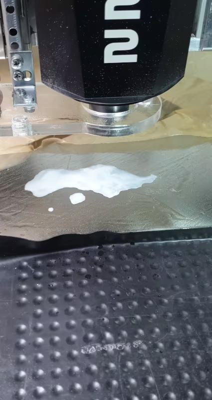 I only work with metal very rarely. Therefore, I don’t have any ready-made cutting or cooling emulsion on hand. As a substitute, I use Ballistol spray and a little water. I rub the oil into the surface. For the
 10x15cm image area, I add about a tablespoon of water.
To my surprise, the two form an emulsion on their own.
I plan to clamp the stock using my vacuum table and position it centrally using locator pins. I close the recesses for handle and stem insert with coated waxed paper (Pro tip! Inexpensive, super tear-resistant, environmentally friendly, almost airtight, easy to work with).
After switching on the vacuum pump, I discover that the armature isn’t sitting completely flat on one side. Instead of -0.7 bar, I’m only getting -0.4 bar. This isn’t critical for the low forces involved in engraving. However, it will be difficult to maintain a consistent line width.
My solution is to scale down the milling design. Due to the smaller size, differences in line width will be hardly noticeable.
Procedure
Before performing the engraving, I run the machine in simulation mode. During this process, I discover two very slow plunge steps. The CAM software likely creates these because of the plunge ramp I set, which it auto-applies to very short lines.
I correct this by manually setting plunge points.
Now I’m running the milling job. The emulsion stays in place despite the spindle fan. The noise level is significantly lower during the first depth of cut than during the second – but it never becomes unpleasant. Vibrations are minimal. Even with the more complex logo, the milling process takes barely five minutes.
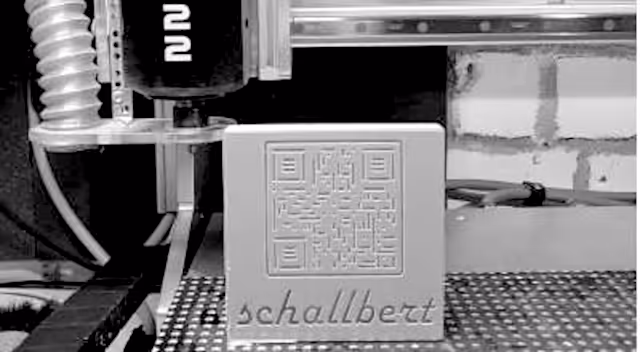
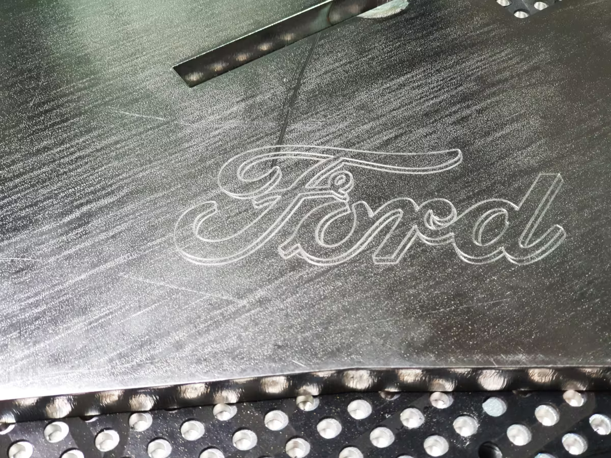
Result
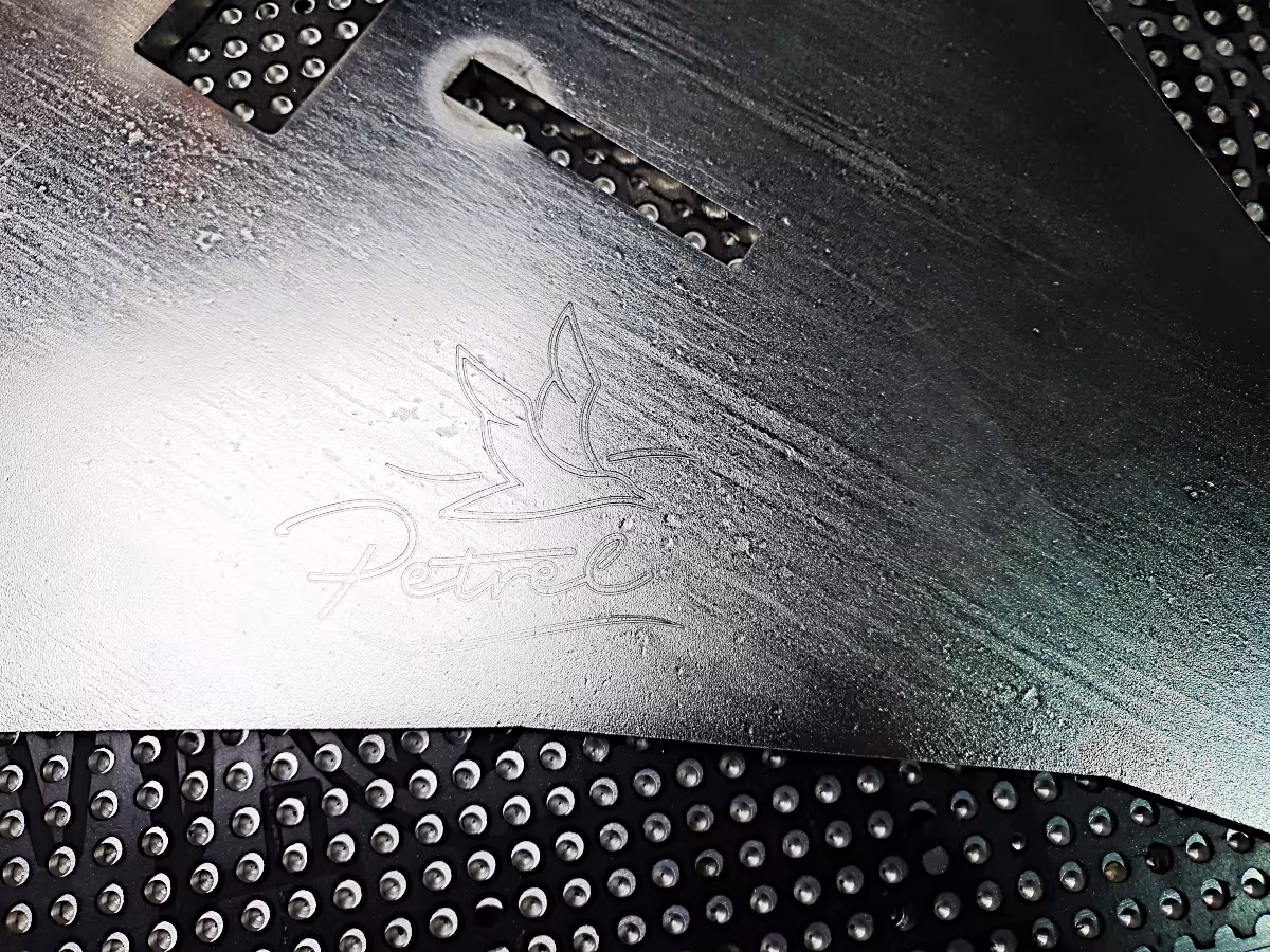
I’m really happy. Based on my observations in the forums, I hadn’t expected such a good result on my hobby machine. Virtually no chatter marks, clean milling channels, and only slight burr formation at the stop and return points. However, the material remains in the milling channel and doesn’t create any perceptible edges. Even in detail, the milled finish is quite attractive.
The following video shows some details of the milling process. My last remaining question: Is the slightly rough noise of the milling cutter during the second depth of cut an indication of increased tool wear due to material hardening?
Engraving Stainless Steel