Multicolor engravings
The project idea
A few weeks ago I was out in the forest. There I saw a beautiful, old sign with the inscription “Help prevent wildfires”. A drawing style like ink from olden times. I took a photo without further ado.
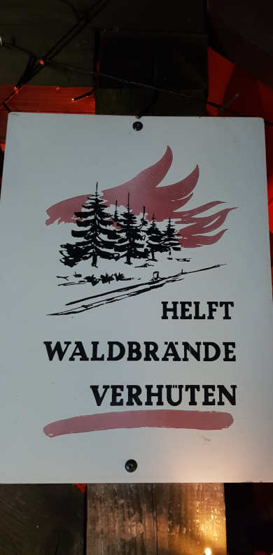
Unfortunately, the sign is quite faded and looks pretty flat as a photo. So I decided to make a three-dimensional copy of the sign with the help of my CNC engraving machine, which would take a little time but not cost much.
From .jpg to .svg
Before I can create a job for the CNC, I have to prepare the image and put it into vector form. My CAM program can’t do much with pixel graphics. I would like to create the image as a “carve”, i.e. use a tapered engraving cutter to carve the areas of the image that should later appear in color. For this I also need a color separation, as the image should later have white, red and black areas in the milled version.
Image preparation
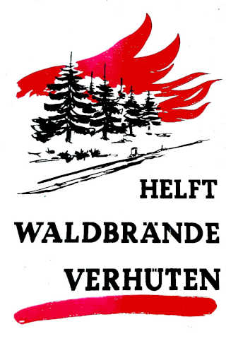 For this I use common image editing programs such as gimp and paint.net. I use the curves tool to increase contrast, straighten the perspective using 3D rotation and then use the crop tool to get the desired image section. I then erase image defects, dirt or artifacts caused by increasing the contrast. Finally, I add a little sharpness and do a tone separation so that I get pure colors rather than red tones or greyscale.
Now I export the image as .jpg and import it into Inkscape.
Path conversion
Here I first scale the image so that it fits on an A4 page. I also create a small 1mm x 1mm square at the bottom left of the image, which will later serve as the zero point for the two color layer images in the CAM, but will not be milled itself.

As already described in an earlier article on path conversion, I use the trace function and can isolate the red and black areas in separate layers using different brightness thresholds. The “red” layer initially also contains the black image areas. However, I can subtract layers from each other so that after this action only the red parts of the image remain.
I then simplify the paths and remove any path artifacts that were created incorrectly. I export the “red” and “black” layers as .svg files.
Path planning in CAM
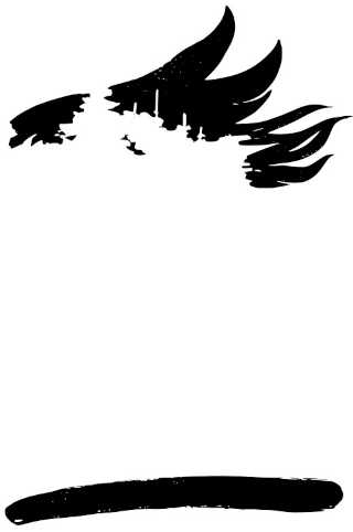 In CAM I have to plan two jobs - one for each color. The unprocessed image areas should appear white. The engraving of the first job will be laid out with red color, and the second engraving should later appear deep black.
So I first import the “red” SVG file, select a scaling appropriate for DIN A4, set the zero point at the bottom left and then start creating the carve paths.
Job1: “red” areas
I set a depth limit of 2mm and select a 6mm 90° graver with one cutting edge and 0.5mm flattening at the tip for the engraving. For clearing larger engraved areas, I select a 3mm two-cutter for wood and mill with 60% lateral feed. I set the speed for both milling cutters to 24000rpm and the feed to 3000mm/min.

Job2: “black” areas
For the black areas, I allow a higher depth of 2.8mm for Job2 and save myself the clearing cutter as fewer connected areas have to be removed here. The greater depth should make the black even darker and the motif more three-dimensional.
Fabrication
For the project, I use a black medium density fiber board (MDF). I paint it several times with white acrylic paint until I have a homogeneous and well-covering surface. After everything has dried, I apply a self-adhesive film. Professionals use stencil films (masking films), e.g. from Orafol, but I make do with a much simpler wrapping film for books. Not perfect, as its adhesion is not sufficient for small areas - but good enough for me.
Red flames
Now I run the first job on the milling machine. To do this, I use double-sided tape to attach the workpiece to the milling machine’s working area and align it properly so that the zero point can be set easily.
As soon as the milling job was complete, I put screws in the T-slots of the base plate on the edges of the workpiece. This allows me to position it with repeatable accuracy. Then I remove it from the machine bed, clean it with a brush and apply red spray paint. Unfortunately, this immediately soaks into the MDF (see video below). The flames therefore remain black. I try again, again without success. So I have to go back to the shop and buy a much more viscous paint to apply with a brush.
If MDF is to be painted, spray paint is not suitable because of its low viscosity: it soaks in and leaves hardly any pigment on the surface.
After waiting again until the flames have dried, I mount the workpiece on the machine bed again.
Black firs
Now I run the second job through. This is significantly faster despite not using the clearing cutter, as there is no need to change tools. I then remove the protective film from the workpiece and clean it thoroughly.
How beautiful the sign turned out!
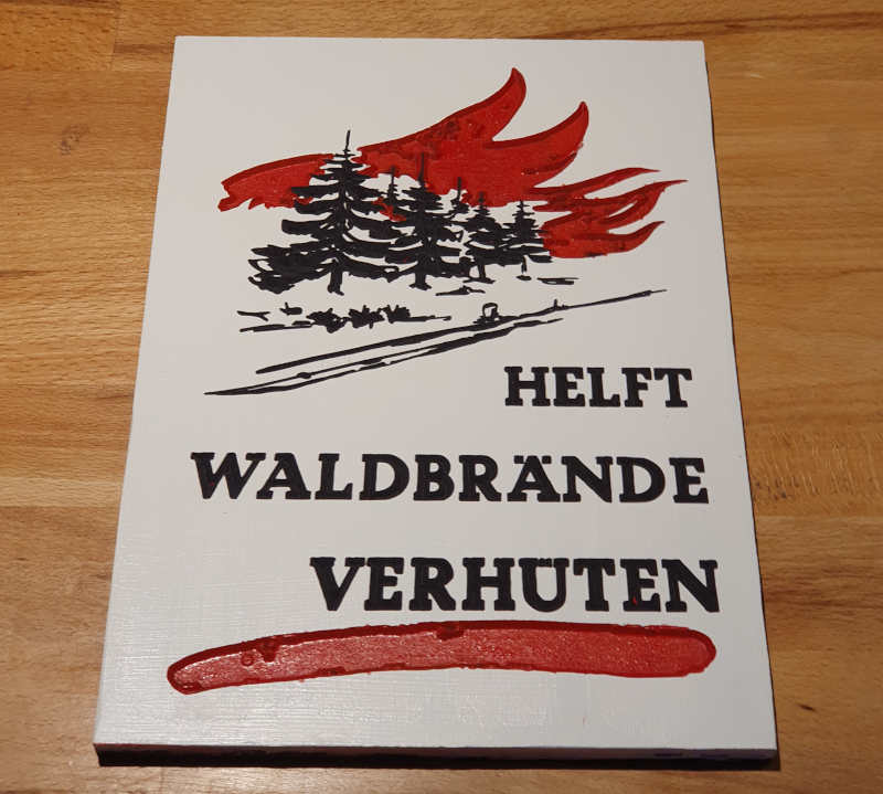
Video of the 3D engraving
There is another time-lapse video for this project, provided on my PeerTube channel.
multicolorEngrave
What could be improved
Looking back, there are often things in my projects that can be done better. When I look at the video, two things stand out to me:
1. Path quality determines milling quality
I wanted to get to the result as quickly as possible and therefore did not remove all path artifacts when converting the pixel image to vector graphics. These appear on the finished product as small islands and points that were milled with less depth than the rest. This is best seen in the red areas of the image. In reality, this is hardly noticeable. In the video, however, you can see that the milling machine needs additional time to work out these areas.
2. CAM strategy costs time
My program for milling planning runs milling paths for clearing, outlines and chiseling from top to bottom, line by line. This means that an incredible number of positioning commands are required for non-connected paths. In the worst case each point is approached three times.
G00 commands are bad here because they take a lot of time and cause the machine to move unnecessarily. This problem can only be solved with a more advanced CAM tool.

