MobFobAmp
Plans
Lists
Tools
| Required tools |
|---|
| Power drill |
| Router, copy ring, rip fence |
| Multi-tool: Sanding, Wood cut, cutter head, compasses |
| Optional: hand-held circular saw with guard rail |
| Hand saw, fine |
| Clamps |
| Chisel, 12mm |
| Hammer |
| Screwdrivers, bits |
| Wood drills: 3mm, 5mm, 6mm, 8mm, 12mm, counterbore 45°, Forstner 30mm |
| Steel drills: 3mm, counterbore 45° |
| Cutter heads: 8mm straight, 12mm straight, 45° optional |
| Soldering iron, solder, shrinking tube, 1m of 0.75mm² cable etc. |
Material list
| Item | Size [mm] | Count | ~ Cost [€] |
|---|---|---|---|
| Front/Back: Birch Multiplex | L 500 B 260 W 12 | 2 | 12 |
| Top/Bottom: Birch Multiplex | L 260 B 248 W 12 | 2 | 4 |
| Sides: Birch Multiplex | L 500 B 110 W 12 | 4 | 8 |
| Strengthening & Mounts | L 260 B 236 W 12 | 1 | 2 |
| Screws (preferably Torx) | 12 x 3 | 100 | 5 |
| Screws (Battery holder, handlebar) | 35 x 4 | 4 | 0.20 |
| Screws & nuts (Speaker) | 15 x M4 | 3 | 0.20 |
| Board holder | d5 x 16 | 14 | 3 |
| Piano hinge | 500 x 32 | 6 | 18 |
| Latches | 50 x 12 | 2 | 9 |
| Bicycle inner tube (Flexible hinges & Straps) | 28” | 1 | 6 |
| “P-Type” Foam or Rubber seal/ gasket | 500 x 9 x 7 | 6 | 8 |
| “P-Type” Foam or Rubber seal/ gasket | 260 x 9 x 7 | 4 | 4 |
| “P-Type” Foam or Rubber seal/ gasket | 236 x 9 x 7 | 4 | 4 |
| “I-Type” Foam Seal (Speaker) | 600 x 9 x 2 | 1 | 2 |
| Aluminium bar | 260 x 12 | 4 | 2 |
| Spacer (Auto-unfold feature) | do 30 di 4 | 4 | 2 |
| Handlebar | What you prefer | 1 | ? |
| Amplifier (e.g. Adafruit 20W Class-D amp) | 1 | 20 | |
| Speaker (e.g. Visaton W 170S 4Ohm) | d170, W 81 | 1 | 35 |
| Battery, 10V - 14V | What you prefer | 1 | ? |
| Fuse, switch, LED, resistors: See Circuit diagram | What you prefer | 1 | ? |
| Spare wood e.g. as mask | e.g. 300 x 300 | 1 | 0 |
| Gum glue or hot melt (airtight gaps) | 20g | 1 | 3 |
The Build
Routing
Let’s first mill all parts so the gaskets for sealing the cabinet can be mounted.
-
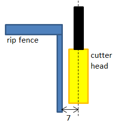 Prepare your router with the
 8mmstraight cutter head@3mmcut depth, and add the rip fence so that the cutter’s center is at7mmdistance from the fence. Make sure to control the router thoroughly so your cuts are straight and clean. -
Continue with the front and back parts,
500 x 260 x 12. Mill the long outer sides of the two boards. -
Now cut the foldable sides of the cabinet. Take two of the four
500 x 110 x 12pieces. Make the long sides face upwards. Use your router to cut the inner sides of these boards like so:
-
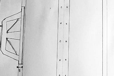
Now it’s time to mill the surrounding gaskets of the top/ bottom parts - mill all 4 of the inner sides. Refer to scetches for help.
-
As we’re at it, exchange the cutting head by the
12mmone. Re-adjust the rip fence so the router will mill with no distance to the fence. Cut the upper “rear” end of the top/ bottom part so that the rubber hinge can be mounted here later. If there are strands like you can see on the image below, gently sand them down with an 180 grain paper.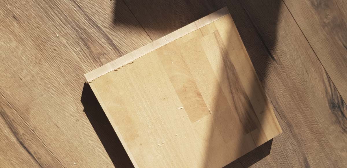
-
Cut the hole for the speaker in the front part. Use the compasses tool attached to the router or the multi tool to cut the inner ring of
148mmdiameter. Three or four steps of router depth variation should be OK. -
Mill a mask with the targeted outer speaker diameter into a spare piece of wood, e.g. height-of-your-copy-ring [mm] multiplex. As you will be using the copy ring to make the bevel, accomodate for its width so you will reach a
170mmfinal diameter. It should look like this now: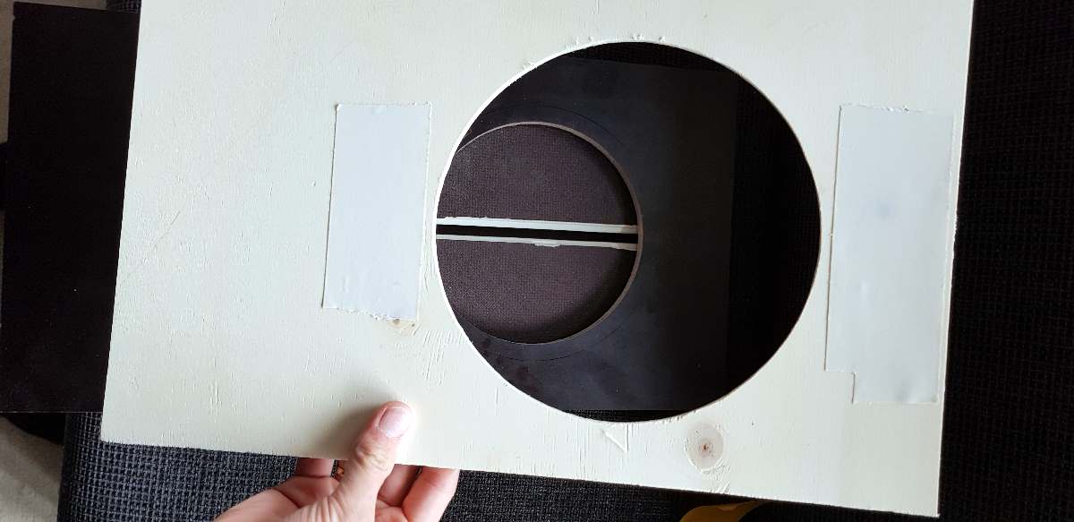
-
Center the mask on the
148mmcutout at the front and atttach it (e.g. use double-sided tape). Mount the copy ring to the router. Make sure you use the12mmcutter head and target a bevel depth of no more than8mm- The speaker has7mmdepth, add1mmfor the gasket. -
Sand the edges a little. Use the multi tool to correct small bumps that might still be left. Repeat until the speaker fits in snugly.
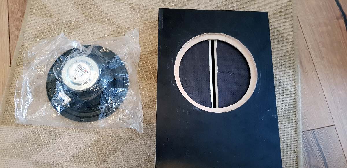
-
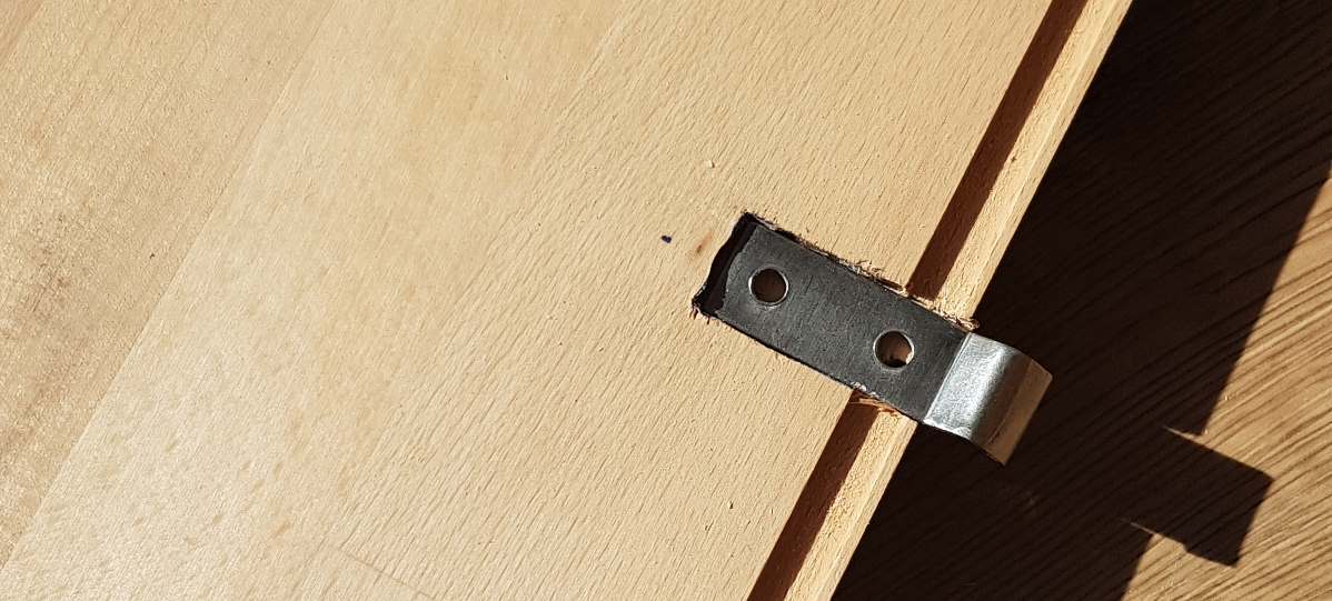
Now cut the notches for the Latches’ counterparts. Set the router to a depth of material + gasket grove depth (so it can sit behind the gasket) and used the rip fence to match the center of the top and bottom parts. Note that you’ll cut orthogonally through the groves for the gaskets you made previously.
Hardware
The hardware is mounted before assembly of the cabinet as the gaskets’s counter pressure will increase difficulty of getting the cabinet shut tight.
- Mount the latches’ counterparts at the top and bottom boards with two
3x12screws each. - Use hot melt or gum glue to seal the metal’s edges against the cutout.
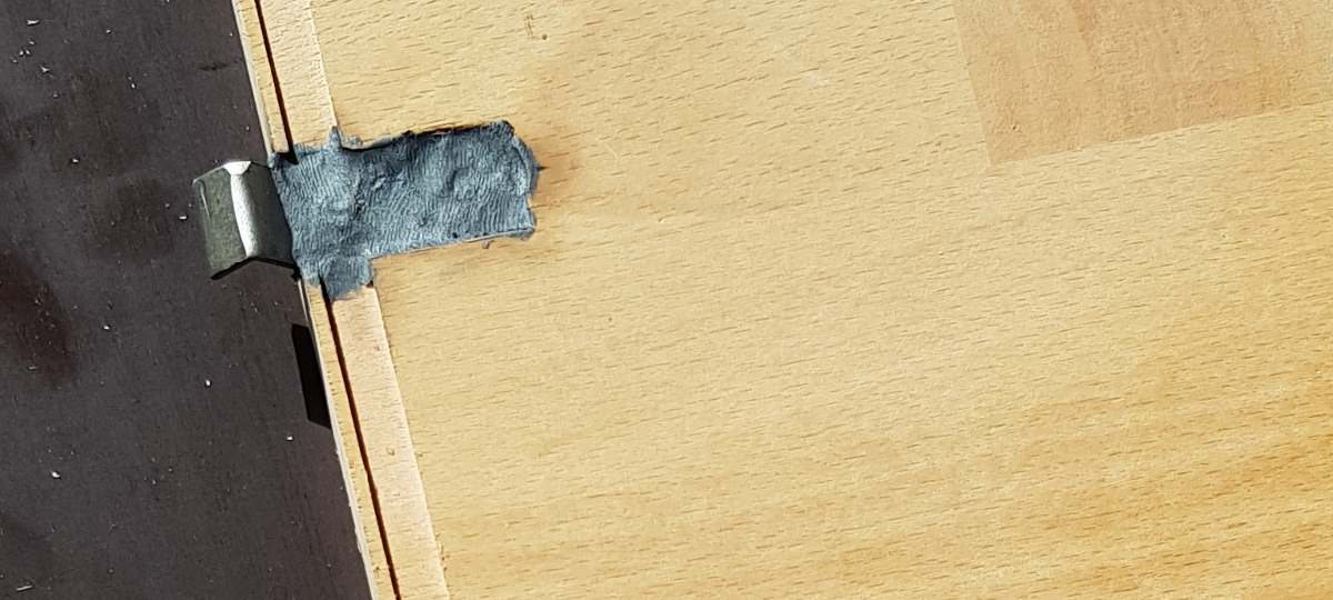
- Cut a piece of
260mmlength from the bicycle inner tube. - Cut this piece in half parallel to the long side, so you get two straps of
260mmlength. - Take the aluminium bars. Cut 5 holes equidistantly into each bar, use the
45°counterbore so the countersunk heads will fit. - Put the strap of the tube below the aluminium bar and mount them at the top rear of the top board.
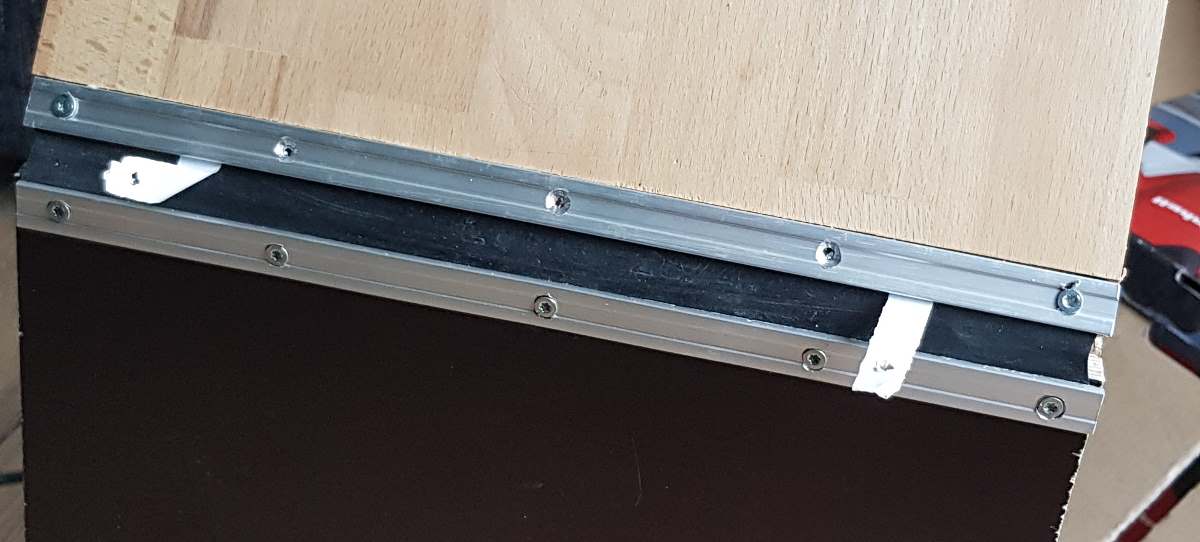
- Repeat step 6 with the bottom board.
- Put Front, Top, and Bottom boards together on the table so they form a big C.
- Mount the latches centered to the front board, make sure they keep the top / bottom “lids” shut tightly and the top/bottom boards are at a
90°angle to the front.
Locators
Now mount the locators aka bottom beam to the top and bottom of the cabinet. They will keep the side parts in place and the cabinet stiff.
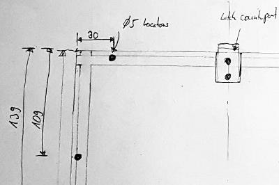
- Mark the spots where locators will be placed at the side of the grove. You can find the dimensions in this section.
- Use a
5mmwood drill and put some tape on to mark8mmdepth so you wouldn’t completely go through the board. - Cut the 6 holes in each of top / bottom board.
- Make sure the collar of the bottom beam is at level with the board surface, not with the grove.
- Remove the locators for now, gaskets will have to be mounted before.
Gaskets
They will finally make the cabinet airtight, but they’ll be under a large strain, especially if you fold and unfold the cabinet often. Some drops of silicon oil might increase their lifetime.
- Make sure the groves are clean and dry so the adhesive tape doesn’t fall off.
- Start with 4 gaskets for each the top/bottom part. They might be a little wider than the grove, use your fingernails to fit them in.
- When finished, take a razor or a knife with a pointed blade to cut holes in the gaskets where the locators will be pushed in. Use the marks for the locator holes you made earlier as guides.
- Use a hammer to gently push the locators through the gaskets into place
- Finally, use a small screwdriver or a blade to raise the gasket like a short sleeve around the locators - the cabinet must be sealed airtight.
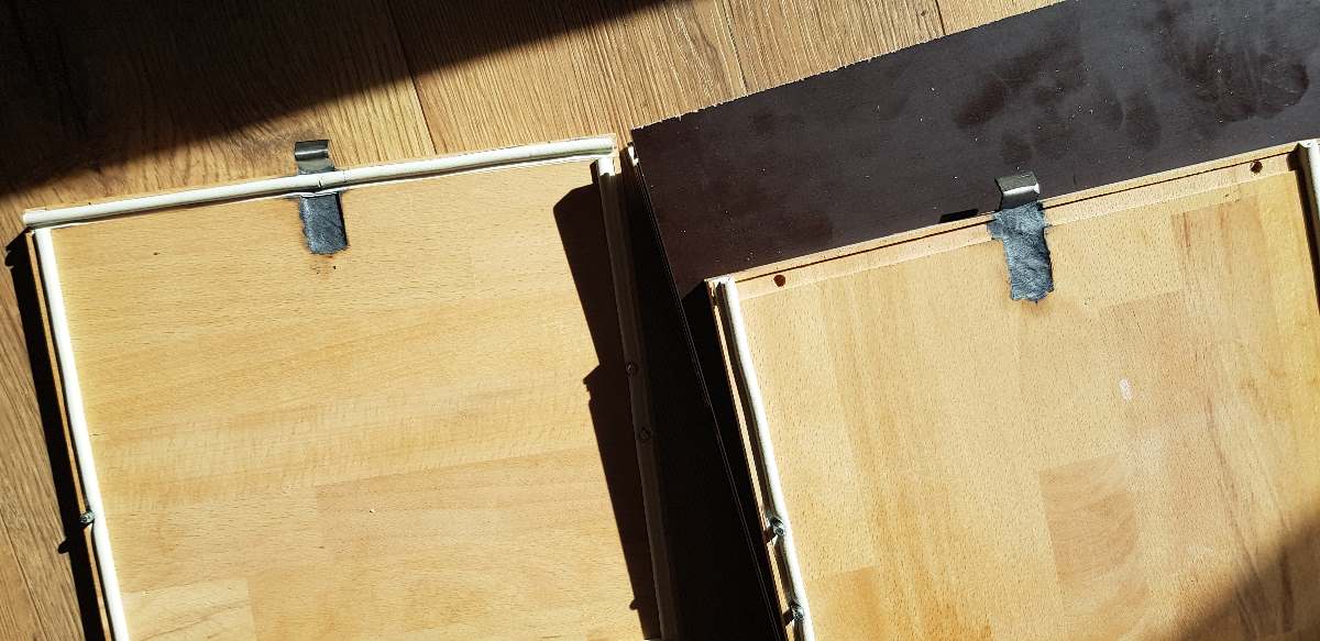
- Apply the gaskets on the two sides.
- Apply two gaskets per front / back board.
Auto-unfold
This is an optional feature. With this installed, the cabinet will always want to unfold by itself and you will have less hassle getting ready to play.
- Take the four sides. With a Forstner bit, cut a
3mmdeep circle right in the center of the insides of the side panels. - Cut a
70mmpiece from the rubber tube. Cut it in half so you yield two straps. - Mount the strap on two of the sides using the
30mmspacer and a screw right within the circle you cut before.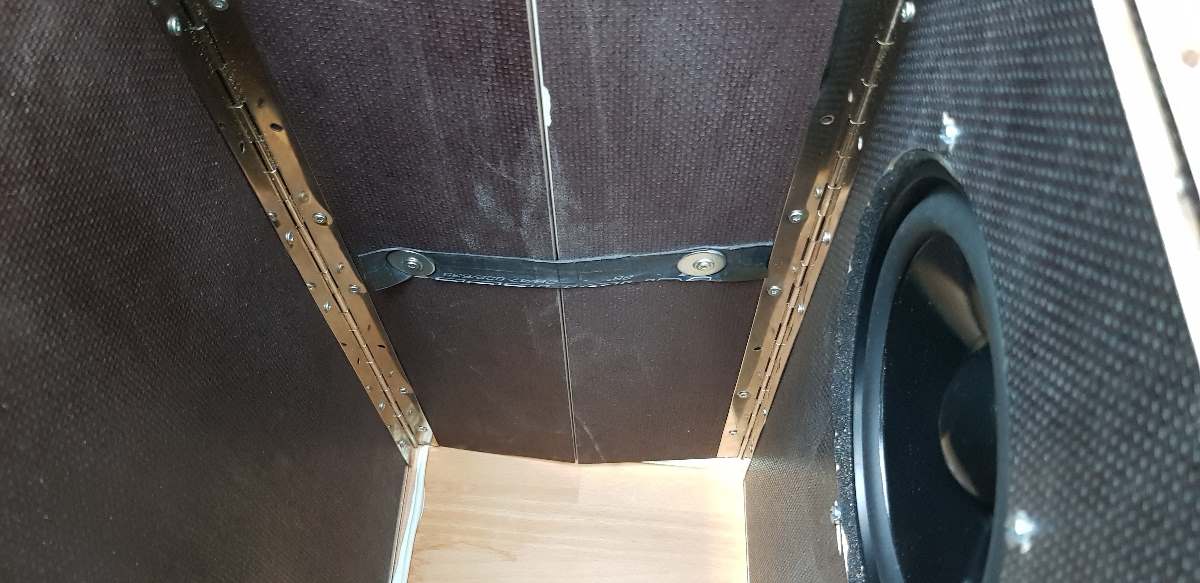
The spacers are needed to increase the area where the rubber strap is secured against the wood. Without them, the rubber would tear around the screw.
Hinges
Mounting the hinges with the gaskets on will be difficult. You might use another pair of hands or some clamps to help you out.
- Put the front panel on the table. Take the two sides with the gaskets on and have them aligned in a way that they “stand” on the gasket of the front board.
 Wile pressing the sides against the front board’s gaskets (orange), put the hinges (red) in place and mark their hole’s positions to simplify mounting.
- Mount the hinges. Make sure there is no gap between side and front panel.
- Repeat with the other two sides and the rear panel.
- Put the two halves together. They will want to move inwards due to the gasket’s pressure, so use the strengthening panel to keep the cabinet fully unfolded. I was using a piece of wood with dimensions of
236 x 27 x 12for this step. - If you prepared the Auto-unfold feature, now is the time to pull the loose ends of the rubber strap and mount them on the opposite side.
- Finally, mount the two hinges on either side of the cabinet’s outer surface. Make sure that there is no gap between the side parts.
- Try the mechanism. If you fold the cabinet, it should unfold by itself in case you have the straps mounted correctly.
Top and Bottom
In this step, the locator holes are cut and the rubber hinge is mounted. This way, only two latches are needed instead of eight and the mechanical pressure on the gaskets is kept high enough.
- Keep the cabinet unfolded.
- Apply some paint on the locators that are mounted in the top/ bottom parts already
- mark the spots to drill locator holes on top and bottom of the cabinet by aligning and then pressing unfolded cabinet shell and top/ bottom parts together
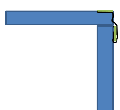 Use the
 5mmdrill to cut the holes both in top and bottom of the cabinet according to the marked dots, depth again8mm.- Check if it all fits fine. Sit on it and try the latches. If the locators don’t fit 100%, take the drill and cheat a bit…
- Mount the top and bottom panels using the two remaining aluminium bars (green) and the loose end of the rubber hinge (black) to the back side of the cabinet like shown in the scetch.
Working?!
Whow, it’s almost done! Folding and unfolding should work by now, and you maybe should hear the sound of this cabinet before doing the finishing work… 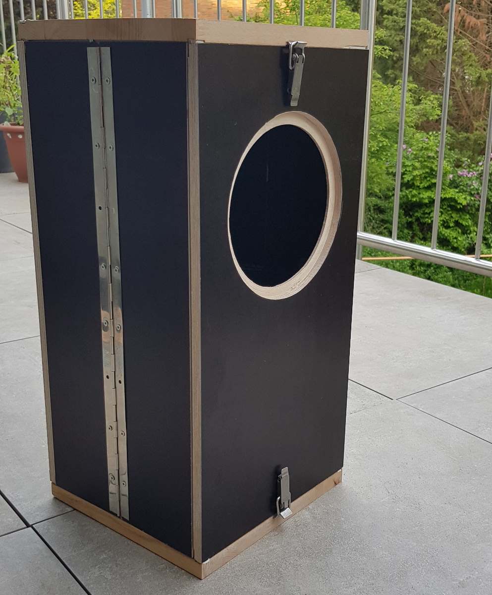
- Mount the speaker, but don’t forget to put in the gasket first.
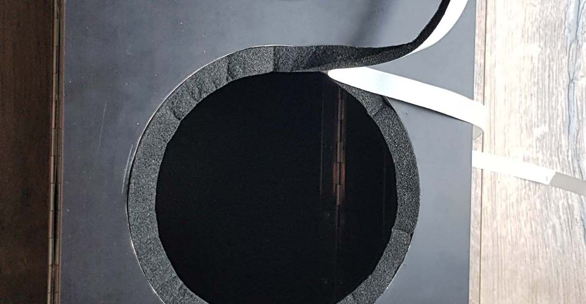 Three machine screws, M4 x15 with nuts will mount the speaker securely.
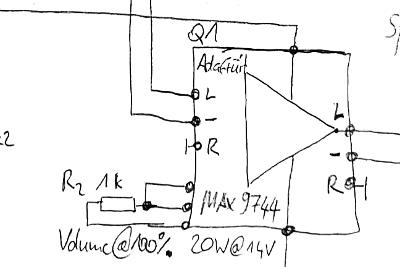
 - Configure the amplifier by soldering some jumpers. Follow the instructions from Adafruit for the analog setup. Mount the potentiometer or set the amp to 100% amplification right away following the circuit diagram
- Fuse and switch might not be needed yet. Instead of a battery, connect a power supply with current regulation, turn it to
12V @ 1Ato protect from short circuits. - Quick, solder a
6.3mminput jack to a couple of wires or an old instrument cable of yours and shove it into the left channel’s terminals of your amp.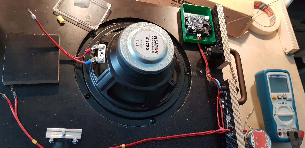
- Connect your instrument.
- Turn the volume of your instrument up and enjoy!
- Note: If your instrument is passive, i.e. has no built-in preamp, you’ll most likely need an additional preamp or an active DI box to get acceptable volume output. E.g. this thing will do the job very well, although most effects pedals also have a preamp onboard - I just used one of the latter.
Finishing the project
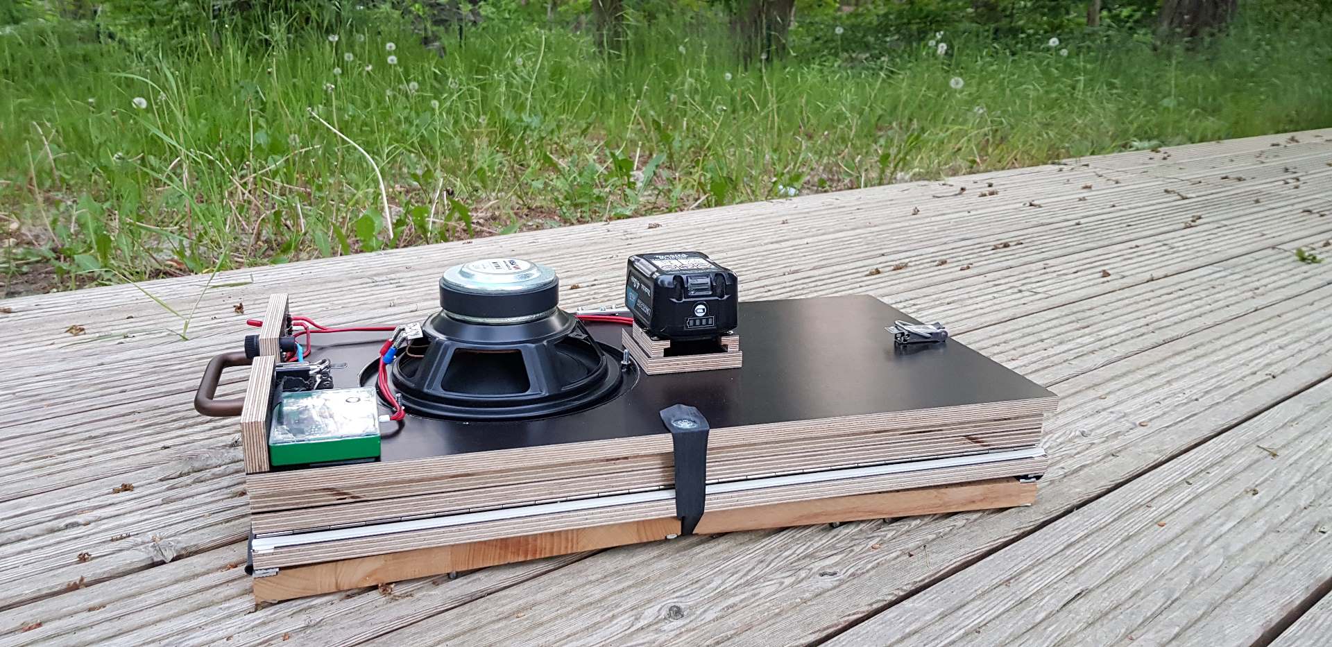
Look how sleek, lightweight and easy to carry your amp is when folded!
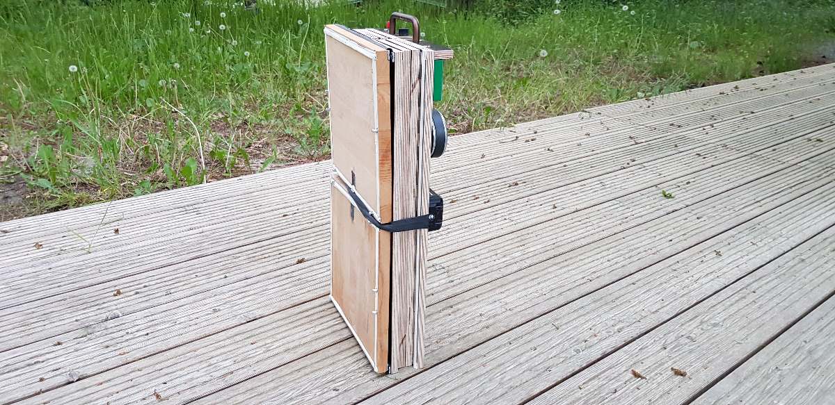
Some additional steps I took were to give the amp an adequate housing (the empty screw case…), add fuse, input jack(s), switch, LED and the battery. If you’re using an electric tool’s battery, normal cable lugs can connect the battery’s terminals to your setup. Using some spare wood and your router, it is an easy job to create a mount you can just click your battery in like I did for my design.
A handle might be a good idea for carrying, and a rubber strap could keep the cabinet in a folded position and the top/bottom parts attached to the rear when folded.
I sincerely hope you enjoyed the read / the build and that you’ll have as much fun taking this little thing anywhere to play as I do.
Schallbert
