Steel sheet (SECC) milling
The Project
This is a PC case made of 0.8mm thick, galvanized steel sheet “SECC”. It dates from the early 2000s and was recently fitted with new internal components.
The Challenge
Due to the now much more powerful graphics card (TDP 200W) and the cramped design as an HTPC, the resulting heat loss could not be dissipated as desired, resulting in temperatures around 50°C inside the case under load. That’s far too high for my liking.
The Specifications
The graphics card follows current, common designs: A metal radiator covers the entire surface of the PCB. Its fins are oriented perpendicular to the socket, and the flat fans mounted on it (3x80mm) push the air through the baffles toward the motherboard and case lid.

Unfortunately, there are only a few millimeters of space between the graphics card and the case lid. Therefore, I want to add extra holes to the lid at precisely this point. The case already has 3mm diameter ventilation holes in a 10x19mm 45° grid pattern on the sides. I will now try to apply this pattern to the ventilation holes for the graphics card. This brings me to a total of 133, which I’d rather not mark, center-punch, and machine by hand for convenience.
So I create a drawing in CAD and then a drilling cycle program for my milling machine.
Tool 1: 3mm Drill Bit
I do have a few hardware store steel drill bits made of standard high-speed steel (HSS) lying around, but some of them are in poor condition. So I use an unused steel drill bit from my Dremel set.
Drilling Parameters
It has a light gray, metallic color and looks so similar to uncoated solid carbide tools that I (mistakenly) assume it is carbide. Therefore, I selected the following parameters:
3mm solid carbide drill bit for steel, 2 flutes: S17000 F470 Z-0.2, retraction 0.5mm
As usual, I work completely dry, meaning I don’t use any coolant.
Drilling Preparation
To prepare the workpiece, I apply masking tape to the section of the housing where the holes will later be drilled. Using the maximum drilling depth, I only penetrate the material minimally. Since the masking tape remains intact this way, I don’t lose vacuum through exposed holes in the vacuum table.
I place the housing cover, outer side down, on the machine bed and cover any unused holes in my vacuum table with a rubber mat. Then I position the gantry close to the holes so that the spindle doesn’t collide with the housing wall during the machining path. I also remove the move to park position G28 from the milling file, as the housing cover is now in the way. After the Z-axis is raised from the last hole, the program ends with M30 (stop and rewind).
The Result
To cut to the chase: The drill bit didn’t last. I noticed something was wrong after just a few seconds from the sound of the machine: It was suddenly much quieter than before.
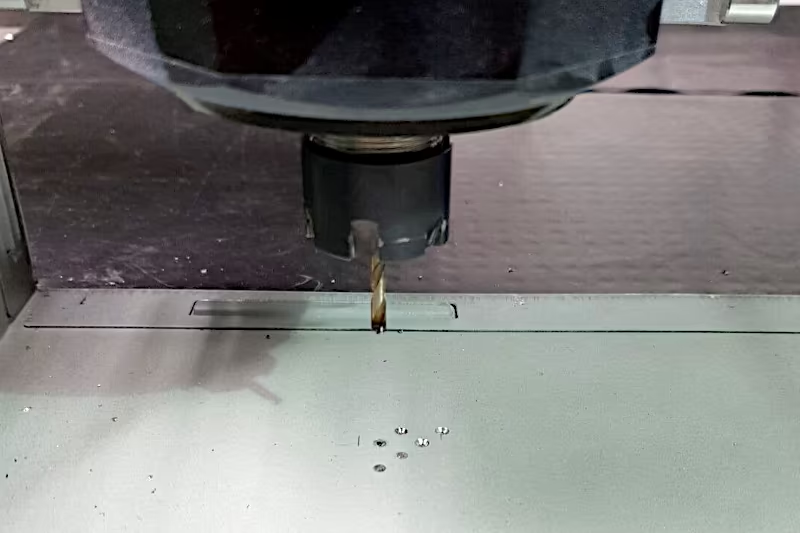
I managed a measly 3 out of 133 holes this way. After that, the tip of the drill bit was stuck in one of the partially completed holes and seemed to be welded to it.
Problem Analysis
Apparently, the drill bit wasn’t made of solid carbide at all, and therefore I was using completely unsuitable parameters. I posted the symptoms in two forums (Hobbyline and cnczone) and received the information that I should have been using S1000 F30 (!) if I wanted to drill a few more holes.
The Solution
 So I’m switching to carbide end mills. I only have one in my collection that was made for steel. However, it has a larger diameter, so I have to adjust my design.
Now I’m creating slots in CAD, which are 6mm wide and 22mm long, positioned at a 45° angle above the graphics card radiator.
Tool 2: 6mm Solid Carbide End Mill
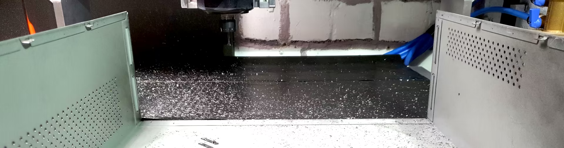
I’m applying my already proven milling technique for SECC and refining it further: High spindle speed, high feed rate, shallow depth of cut.
6mm solid carbide end mill, AlTiN-coated, 2 flutes, 0.2mm 45° chamfer: S10600 F880 Z-0.18
Cutting SECC steel of my PC case
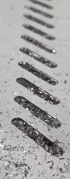
Cut Quality
The cut edges are burr-free, high-gloss, and razor-sharp. Therefore, a chamfer needs to be applied. I do this by hand with a scraper and utility knife, which I quickly regret: I can’t get it as clean and even as I’d like.

Not so bad: I get a neatly finished case with significantly improved cooling practically for free (apart from the learning curve). In the image above, the graphics card’s radiator is clearly visible through the new slots in the case.