Milling steel
For our retro gaming booth at the Maker Faire Ruhr 2024 I milled cutouts in PC cases. I would now like to tell the story behind and share suitable parameters for machining steel on “soft” hobby machines.
But be careful!
First of all, I would like to mention that I made some safety-related stupid mistakes that should definitely be avoided in the future:
- Never handle rotating machine parts with gloves on!1
- Coolants and lubricants must be suitable for the intended purpose; risk of smoke and fire!
- Protective and barrier devices must be firmly mounted and must not be bypassed!
So if you are dedicated to occupational and operational safety, you should not watch the video provided below.
The workpiece
I have to work on steel sheets from PC cases (MIDI towers) with a thickness of 0.7mm-0.9mm. The material is galvanized, cold-rolled steel (SECC), i.e. a cheap and relatively easy-to-work type of steel with a low carbon content and a small admixture of other alloying elements.
 This type of steel is used for sheet metal in automobile construction and many household appliances, especially in “white goods”, and is also often used in vending machine and switchboard construction. This milling work can therefore be transferred to various other areas of application.
The dimensions of the housing sides are between 35x45xm and 52x50cm, so they all fit on my machine. With one exception, the side panels lie flat with their visible side and without cutouts, so my vacuum table can easily be used to hold them down.
The side wall of a housing has gill-like perforations for ventilation and a recess for a handle. For the grille I use cling film to maintain the vacuum pressure, while the loss of vacuum is accepted when milling the handle recess.
CAD/CAM
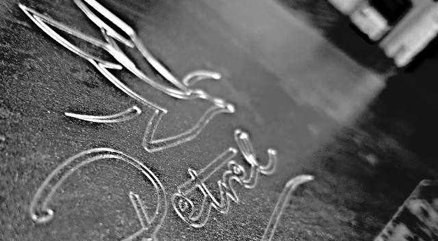
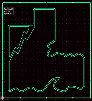
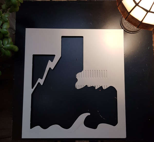
The cutouts to be made are all geometrically simple and take into account r=1.5*milling radius for curves. The window for the “sea PC” is designed in two parts and is intended to represent a storm scene at sea.
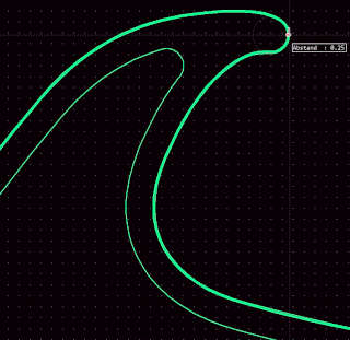 The window is
 0.25mm smaller all around than the recess, which results in an almost play-free fit and looks very professional.
In the CAM I set up counter-rotating milling, which is advisable for less rigid machines like mine when machining hard and tough materials. The machine runs a little smoother and quieter this way - but it still shakes and vibrates considerably.
For the depth of cut, I choose a value that is four hundredths of a millimeter less than the material thickness. This way, I practically only leave a wafer-thin film of paint and corrosion protection, but I don’t wear out the adhesion promoter mat.
Milling parameters
 Compared to machining wood, the cutting speeds for steel are significantly lower. While I can work with
 450m/min in birch multiplex, various cutting data calculators like this one recommend values between 80m/min and 200m/min. This results in a parameter set like S4250u/min, F255mm/min for my two-cutter made of micro-grain carbide, for example.
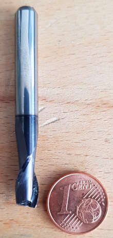
This cutter has cutting edges bevelled at a 45° angle of 0.2mm in length and a helix of 30°. To increase the service life, it is coated with a TiAlN alloy approximately 3µm thick using the vacuum process PVD.
After consulting the cutter manufacturer, I preselected parameters on my machine, which I then adjusted in test runs and was thus able to achieve a higher depth of cut at a lower chip temperature (no more blue chips). Here are the values that I ultimately used for machining:
| Milling cutter | Cutter geometry | Speed | Feedrate XY | Feedrate Z | Depth per pass |
|---|---|---|---|---|---|
| 6mm, Solid Carbide | 2Flutes 30°, l=12, 45°0.2Fase | 6000u/min | 550mm/min | 250mm/min | 0.8mm |
Update milling parameters
After a few questions in various forums on the subject, I have gained new insights that will significantly change my milling parameters for future projects. These are:
- When machining steel, pay attention to beveled cutting edges for the milling cutters
- Increase the feed rate, reduce the depth of cut (especially applies to “soft” machines)
- Dry milling is less problematic than I thought
This Youtube video by Stefan Gotteswinter explains very clearly the advantage of lower chip thicknesses when using beveled cutting edges. This works best when the depth of cut is not greater than the length of the bevel at the end of the cutting edge. I am also advised on cnczone to choose a “high-speed milling” approach.
For my two-cutter, I adjust the cutting data so that I drastically reduce the depth of cut, but increase the feed and speed:
| Milling cutter | Cutter geometry | Speed | Feed XY | Feed Z | Depth per pass |
|---|---|---|---|---|---|
| 6mm two-cutter | 2Flutes 30°, l=12, 45°0.2chamfer | 10600rpm | 970mm/min | 450mm/min | 0.2mm |
I am really looking forward to testing these values in practice.
Preparing the milling process
As this is my first time working with steel, I had to run a few errands and try things out beforehand.
Cooling lubricant
Cooling is essential here to protect the milling cutter, says the milling cutter manufacturer. So I got myself a syringe with which I can apply lubricant precisely. But: which product should I choose?
For just three parts, I don’t buy a minimum quantity lubrication or cooling lubricants from industrial supplies. So I try out products available at home:
- Spray lubricant WD40: Not suitable for me. Evaporates quickly, smells.
- Sewing machine oil / fine oil: Not suitable. Very liquid (flows into vacuum holes), smokes and stinks.
- Rapeseed oil for frying: Wonderful! Lubricates well, relatively viscous, low odor, hardly any smoke development.
Chip protection
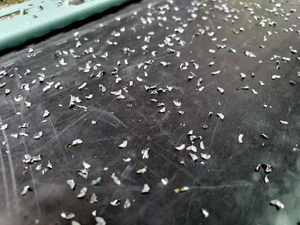
 The metal chips created during processing are short, hot and sharp-edged. They tend to get caught in clothing and fly so far that even at a distance of more than a meter from the machine, plenty of chips still arrive.
So I sawed off a segment from an acrylic glass tube with a diameter of 20cm, slotted it and hung it on the Z-axis as a chip protection.
My mistake here: I relied on the Acrylic’s clamping force alone and did not additionally attach the chip protection with screws. Fortunately, it only jammed when the last part was being made.
Milling
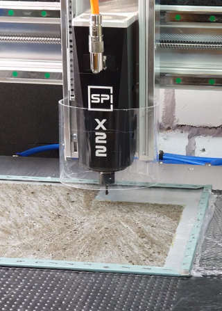
You’ll notice immediately that the machine does not have the necessary rigidity to process steel. As soon as the milling cutter plunges into the material, the machine begins to rattle and shake. Nevertheless, it bravely fights its way through the material, while I am always ready with a drop of oil at the milling path.
Milling Steel!
The spindle has more than enough reserves available even at the low speed. However, when positioning the workpiece, I make sure to work as centrally as possible on the ball screw of the Y-axis. This is where the machine experiences the least torsional forces. The chips look good to my eyes.
The noise changes when milling: I have more vibrations in the machine when I mill in the Y direction than when only the X-axis moves. I will look into this phenomenon in more detail later.
The result
After machining on the CNC, I can simply cut out the windows with a cutter knife.
Video: Cutting the cutout with a cutter knife
I quickly remove the (minimal) burrs with a file.
Then I make windows out of transparent acrylic glass, thickness 3mm, which I provide with a 10mm wide fold at depth of 1mm all around. This takes into account the thickness of the double-sided adhesive tape for fitting and the pane sits flush with the PC case.
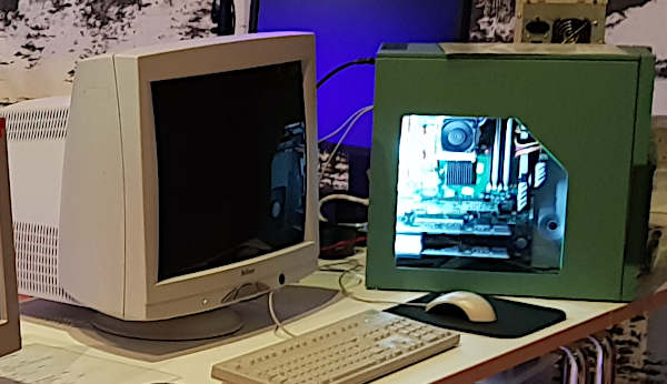
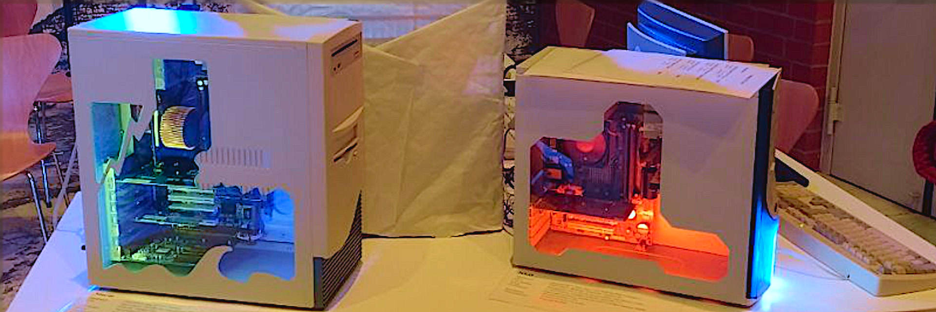
The picture above shows a Celsius 1000 Workstation case from Siemens, which now looks really classy with a simple window.
-
Gloves can be torn away if they accidentally come into contact with the milling cutter. This can result in serious hand injuries. ↩