Spindle upgrade
Project stats
- Difficulty: Expert 5/5
- Cost: ~2700€
- Time: ~20h
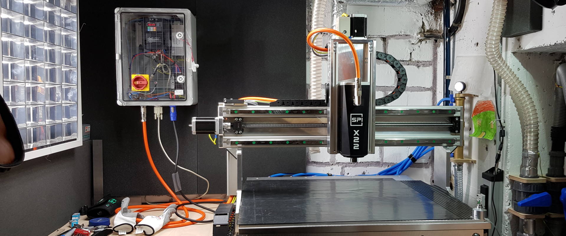
Upgrading my CNC’s spindle
In contrast to my statements here I decided to invest in a High-Frequency spindle. I went through a lot of reading, building and testing effort before I could finally create chips with the new setup.
Why I upgraded
There are strong and weak arguments for such an upgrade. Long story short: My arguments were rather weak so I could have sticked to the router motor I already had collected experience with. The decision to upgrade anyways was on the non-rationale side.
Strong arguments to upgrade 🥰
- More power: This is not supposed to happen again, and I can run high feed rates with confidence. As a result, machining time reduces for projects that require removing loads of material.
- More low-end torque: With a face mill cutter, the router motor tended to overheat as the bolt-on fan wouldn’t provide enough cooling at low rotation speeds.
- Vibrations: I hope that the vibration issue is gone now because both spindle, its attachment to the Z-axis, and vacuum table provide the CNC with higher stiffness.
- Likely higher precision of cut on the spindle due to higher-grade bearings and more rigid design
Weak arguments to upgrade 🤔
- I was very interested in variable frequency drive and spindle technology
- I liked the looks of the Spinogy spindle.
- I was in contact with Spinogy for half a year discussing possible configurations and the adaptation to my machine and I didn’t want to let them down
- The VFD has internal safety systems that reduce probability of damaged workpieces
- The HF-spindle is more quiet than a router motor
Arguments not to upgrade 🤨
- Low value add for money: Versatility of the machine is increased by just a little while upgrade costs are really high
- Spindle warm-up takes
30 minutes, a considerable amount of time when you’re not using the machine 24/7 - Steep learning curve required for configuring VFD/Spindle, >400 pages of VFD and spindle manuals to read, circuit layouts to plan, and a switching cabinet to build.
- The CNC frame I have is laid out for light to medium usage. Turning up the feedrates because of the new spindle’s capabilities could overburden frame and structure, especially the machine’s weak spot, the Z-axis.
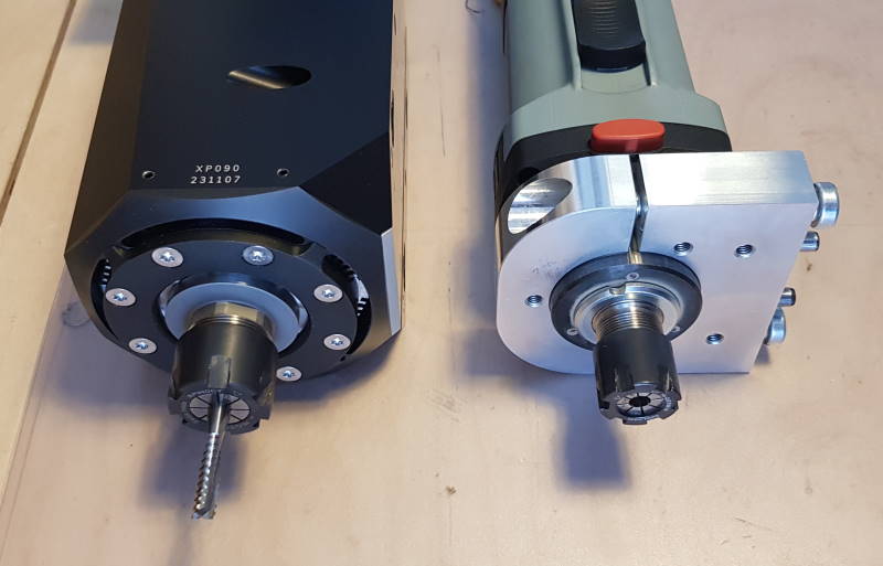
- The HF-spindle weighs 3x more compared to the router motor.
- A VFD system makes the whole CNC much more complex and adds a multitude of paths for disturbances.
All in all the spindle is overpowered for the rest of the machine and the benefit for adding the spindle likely will be low. You see this was an emotional decision. I hope I won’t regret it.
Auto tool change?
If I had a well-running woodworking business with clear scope and just a few endmills in use, I’d have decided to invest the extra money.
For my prototyping usage on the other hand the hypothesis I made in the past still holds true. I’m using a lot of different endmills as I’m working with many materials that each require a unique set of tools. The cost of steep taper toolholders I’d require to cover my work would have exceeded the cost of the spindle.
Instead, I bought some more spindle nuts. This way, I can keep the most-often used collets attached to their nuts, reducing the time required for a tool change.
Cost 💶
I made some other decisions to both match my way of intermittently operating the machine as a sideline and to keep cost down. In my spindle configuration, I selected the 1.5kW low power option and did not raise specs of the bearings so the machine is limited to 30kRPM. I chose forced air cooling over the water-cooled option and did not invest in a continuous temperature monitoring system.
Still, total system cost are more than 2x spindle cost. Note that although the VFD is not too expensive, shielded motor wiring, connectors, torque wrench, line filter, collets/nuts, the switchbox and many additional, small parts add up to that high of a number.
Information phase
To get the new spindle running I had to plan, build, and configure a complete subsystem that involves spindle drive, cooling, auxiliary power supply. Driven by the project complexity, I executed my work in different phases that would build on top of each other. Starting with the information phase, let’s go through some of the questions I had to find answers to.
Variable Frequency Drive
 As I wrote in this article, a VFD is used to control rotational speed of a HF-spindle. The motor is called like that because it operates well above grid frequency (
50Hz in my region) to reach higher rotation speeds as required by the application, especially when working with smaller endmills.
When I took a deep dive into that topic for my new spindle application, I had a phone call with Mr. Wagner from Omron (VFD manufacturer) to answer some of my questions.
U/f characteristic or sensorless vector control?
- Selecting
U/f characteristicwill make the VFD reduce voltage along with the frequency as long as the motor operates below its corner frequency (which for my machine is400Hz). This is because the inductance of the stator wires reduces with lower frequency. That in turn increases the current flow through the stator, and along with it torque and power dissipation rises. So in the end, by applying theU/f characteristic, current and with it the torque is kept constant. At very slow speeds though, the inductance becomes so low in comparison to the stator resistance that torque decreases over-proportionally which makes this option a bad choice when operating in that low-speed area. At or above the motor’s corner frequency on the other hand, voltage is kept stable and just the frequency is increased which reduces torque. - With
sensorless vector control, the VFD uses a mathematical model of the motor it drives to calculate optimal switching times to always achieve nominal (or even above) motor torque independently of the motor’s rotational speed. It is especially useful for applications that require heavy starting like elevators etc. and often requires the user to perform a VFD auto-calibration run with the motor connected.
Here’s a link to somebody’s youtube video in which the two options are compared at low speeds. Here’s another one that demonstrates how the VFD even goes beyond nominal motor torque when load is applied.
As most of the endmills I use demand a speed of 15000rpm or higher, I likely won’t feel the drawbacks of the U/f characteristic. Plus, on my VFD, the sensorless vector control option is only available up to 400Hz so I would only be able to use 80% of the spindle’s speed range. Easy decision: U/f it is.
freewheeling, brake resistor usage or energy recovery system?
For braking the motor, the VFD can be configured with different options. When allowing the motor to freewheel in standard setting, it may take a long time until which the spindle has stopped from full speed.
When a brake resistor is configured like I do with my spindle application, braking down takes two seconds only. I also configured the DC brake to completely bring the shaft to a halt.
For more powerful motors or applications that involve movement of high masses, an energy recovery system might make sense. It is connected to the VFD’s intermediate circuit and is able to supply power generated through the motor’s excess motion energy back to grid. To use this feature, an additional electrical device is necessary and compabibility of the VFD’s intermediate circuit with that device has to be made sure. This adds high cost to the system and only pays off when large amounts of energy can be recuperated.
Which modulation freqency / clock frequency should I use?
The clock / modulation / carrier frequency is the rate at which the power transistors within the VFD switch to provide an output voltage for the motor that resembles a sine wave. On my VFD, it can be configured in a range of 2-15kHz.
To select an optimal frequency, a balance is to be found between multiple factors:
- Transistor switching losses rise at higher frequencies.
- Transistor on-state losses rise at lower frequencies.
- The human ear is especially sensitive in the range of
2-5kHz. - Resonance frequency of the motor system should be avoided.
- Electromagnetic interference emissions rise at higher frequencies.
Of course, if your motor manufacturer makes a modulation frequency recommendation, you should follow that one. I played around with different values and chose 5kHz as a good compromise between the above factors. I also felt it sounded better than 6 or 4 kHz on my machine.
Can I control the coolant fan based on spindle temperature?
Yes, that is possible. All you need are a continuous (non-switching) type of temperature sensor, e.g. PT100 or other thermocouple, a measuring transmitter, and a free analog input of your VFD that can be configured to on-off control one of the free digital output ports that then switches a relay the cooling fan has to be connected to.
My motor, unfortunately, is equipped with a switching-type thermistor that connects to the VFD via a temperature alarm input. Thus it can shut the system down once an over-temperature event occurs but is not suitable for a continuous temperature monitoring/control of the cooling fan.
Is 18V enough to detect HIGH on a 24V digital input?
Yes, on my VFD I was able to feed a lower voltage than the targeted 24V to a logic input and still make it detect HIGH level.
Can I connect VFD logic ground to my DC supply ground without issues?
Yes. I did and there were no issues. I even had to do so because my ‘Run’ input is potential-free so I had to connect it to the DC power supply’s positive voltage rail over a relay contact. Also my numerical controller’s analogue output voltage to control spindle speed is forced to use the same ground reference as the VFD, so it’s also connected to the VFD’s logic ground.
What do I need to consider regarding electromagnetic compatibility?
- Use a line filter between mains switch and VFD.
- Use shielded cables for the motor you connect.
- Keep motor cable as short as possible.
- If you have to use long cables, add a HF noise filter.
- Have the shield connected to the VFD’s protective earth panel along with the motor’s protective earth leads.
- Make sure the shield establishes conductive contact to the cable connectors.
- Perform a continuity test.
- Make sure the switchbox has one central protective earth clamp where every device within the switchbox connects to.
- Make sure your supply’s protective earth is connected to that clamp, too.
- When wiring the switchbox, position motor cables as far away as possible from low-voltage signal wires.
- Use a metal switchbox housing (connected to the central earth point, of course) or at least a metallic carrier plate you mount all devices to. This will reduce radiated electromagnetic interferences.
Spindle
To select a matching spindle for your machine and application, there are a few points to consider - independently of the motor type.
Power
The spindle power maybe is less important than you might think. I’ll give some examples you can follow to choose a good match.
<=400WHF-Spindle or<=800Wrouter motor: You have a hobbyist machine and do not require to run it blazingly fast. It is fine for you to go shallow or medium depth per pass on hard to cut materials like aluminium or HPL. Your machine frame weighs less than60kgand is relatively big for its weight, e.g. workbed surface of>=0.5m².<=700WHF-Spindle or<=1200Wrouter motor: Your machine weighs more or is more stiff than the above option. You use bits bigger than6mmin diameter a lot, or have to machine parts with face-milling cutters often. Your Z-axis is strong and you feel your machine is bored when running through hard wood at3000mm/min,Z+6mmwith a6mmcutter.1.1kW / 1.5kWHF-Spindle: You have a compact machine (around500x500mmtravel, weight:100kg) and do want it to finish its jobs quickly, cutting aluminium or wood at higher feed rates. When working with wood, you use roughers a lot to save time. Your machine can handle higher accelerations and rapid movements (e.g.1000mm/s²and300mm/s).>=2.2kW: You left the hobby sector - likely forever - both with your machine and the order bank that has piled up on your desk. You have a workshop, a professional dust collection, and an heavier machine you trust to run all day long without intense supervision. You might consider this blog as “too basic” and head off to new shores where people can really help you as a professional.
Weight
Weight scales with power. An 800W router motor can come at below 2kg including mount while a 2.2kW HF-Spindle with automatic tool change might be at or above 6.5kg without tool holder. Footprint and cables also tend to become larger.
A high weight can negatively affect light machines, especially. In an extreme case, the Z-axis might start moving down when the stepper motor is not energized and machine acceleration, especially at the portal movement axis, might have to be reduced so no steps are lost. Also keep in mind that heavier machines tend to be bigger, so the cutting forces can have unfavorable effects on the Z-axis due to increased leverage.
2-pole or 4-pole design?
If you need a lot of torque, especially at low speeds, chose a 4-pole design. Keep in mind that you will require double the frequency to have it turn with the same RPM as a 2-pole motor. If you often run your machine at high RPM instead, consider buying a 2-pole spindle.
Water or air-cooled?
This again is more a question of cost and professionality than anything else. Of couse, bolt-on fan self-cooling works fine. Forced-air cooling comes a little more expensive but is likely more quiet, its main advantage being that the spindle does not get too warm independently of its speed of rotation.
A water cooling solution removes heat from the motor more efficiently and the water’s high heat capacity leads to homogenous temperatures in the whole spindle. It dampenes vibrations and is the quietest cooling solution of all. On the other hand, the system is much more expensive, more complex, takes more space for pump, radiator and equalizing tank etc., and requires maintenance.
The planning phase
After studying the manuals of all the parts I had ordered, I created a schematic circuit diagram for the spindle subsystem.
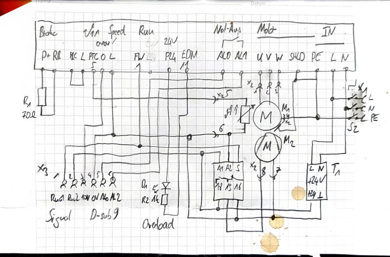
At the top you see the VFD with its terminals. X1 is the mains power input with disconnector switch S2. X2 connects spindle to the VFD and X3 is the signal port to the CNC. In the lower right, there’s a DC power supply T1 that feeds the forced-air cooling and provides a logic voltage rail. The spindle M1 motor’s temperature is monitored by the thermistor R3 (where I forgot to add the label.) The spindle cooling motor M2 is controlled by a time relay which is in turn controlled through the RUN signal. A digital multi-purpose output is connected to a red LED D1 that is configured to light up if an overload warning is present.
The circuit plan remains pretty straight-forward. So i did not invest time into neat drawings. To make it look even more authentic, I spilled some ☕ on the paper.
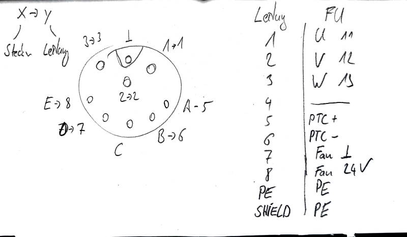
This is the pinout of the spindle connector X2 and its corresponding terminal on the VFD. It was useful several times when adding connectors to the shielded motor cable (orange in color, ref. to banner image at the top), and during unit testing.
I noted down the fastening torque requirements for each screw including the terminals and prepared the tools I’d require to both prepare the switchbox’s in- and outlets and air vents, as well as the mount and wiring setup.
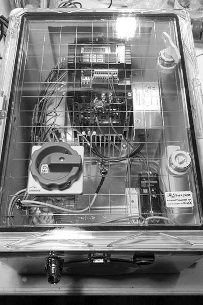
The construction phase
Spindle VFD Cabinet build
Commisioning
Before taking the system into productive use, I ran the test plan. When it was complete, I executed a Spindle grease distribution run according to the manufacturer’s instructions.
Then, I calibrated the 0-10V analog out in my CNC software to match VFD frequency / spindle RPM. Example: S10000 should generate 3.33V at the output and make the VFD run at a frequency of around 175Hz to account for slip.
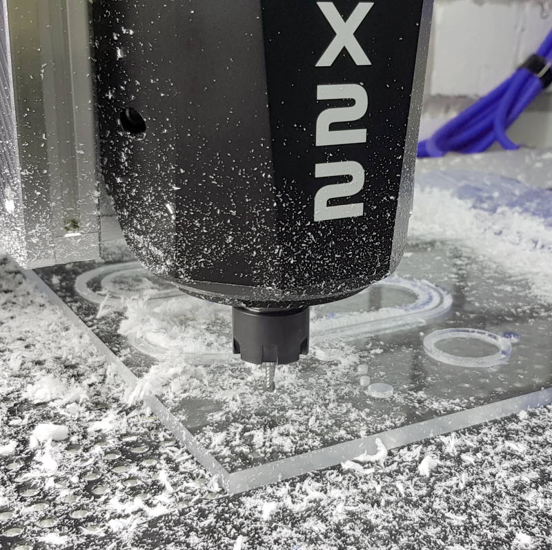
Finally, I was able to run some light jobs to see that the system works as intended: 8mm PMMA, full slot, single pass in Z+=8mm, 4mm single flute (polished) carbide cutter at S=26kRPM and F=3000mmm/min
The analysis phase
This phase will follow later, maybe a year into working with the new spindle. I’ll have a look at the following:
- Was the investment worth it (roughly 8x more expensive than a router motor)?
- Did I use the additional capabilities (higher power & more RPM)?
- Does it produce noticeably better quality results?
- Is it more reliable and requires less maintenance to my previous motor?
But what I already now can say: I learned a lot, it was fun designing, wiring, setting up the system, and exciting to actually see it worked out as I intended 🙂