Vacuum Pump
What is it?
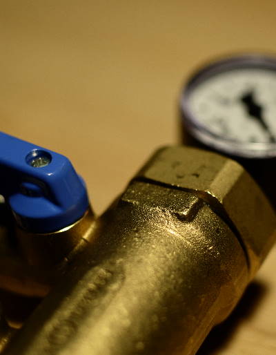 A vacuum pump is an appliance that is able to evacuate a vessel, i.e., to reduce the amount of gas atoms within a container. It does not seem to be possible to shrink the number of atoms within to 0, but of course this is by far not required for our application in which a so-called technical coarse vacuum is sufficient.
There are different types of vacuum pumps with specific properties that I’ll try to shed a light on later.
How does it clamp workpieces?
For clamping with the use of a vacuum table (see my related post), we’re only interested in the pressure difference the vacuum pump generates versus ambient pressure which is (103000Pa = 10.3N/cm² = 1kg/cm²). This is the maximum clamping force a vacuum table can generate in theory.
Pump capacity vs. vacuum pressure
The key parameters of any vacuum pump are the minimum absolute pressure they are able to draw in hPa (at low or even zero throughput) and the volume of air they’re able to put through within a given time in m³/h (at low or zero pressure difference).
This is comparable to the electrical world, where open circuit voltage (pressure difference) and short circuit current (throughput) e.g. in photovoltaic cells are given parameters to calculate an optimal point of operation.
Here, you can add more cells to either get more current or more voltage from the system by connecting them together in parallel or in series. For vacuum pumps, it’s often more practical to choose a more powerful motor that drives the pump than using series/parallel operation. But still, there’s a trade-off to make. Certain pump types are very well suited to generate lots of throughput, but then are lacking vacuum pressure and vice versa, pumps that have very good vacuum ratings often have considerably less throughput than other pump types with the same power level.
If you want both, prepare to spend a lot of money. So again, it all comes down to what you need for your application.
Pump characteristics
Max. Volume and max. pressure difference can be entered as data points in a XY-diagram, and a line can be drawn between these two points which gives an approximation of overall pump behavior. While the position of these points largely depend on the pump’s motor power, the line’s slope is determined by pump type and design.
Below find a comparison of these different pump types. For this example, I arbitrarily chose a motor power of 1.5kW and selected some pumps with that rating of which I could find datasheets online.
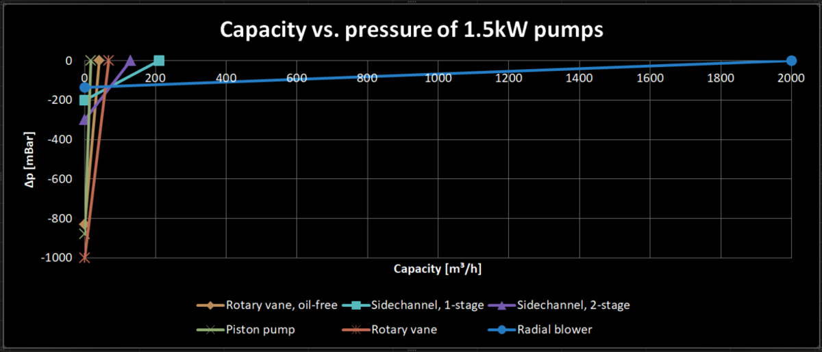
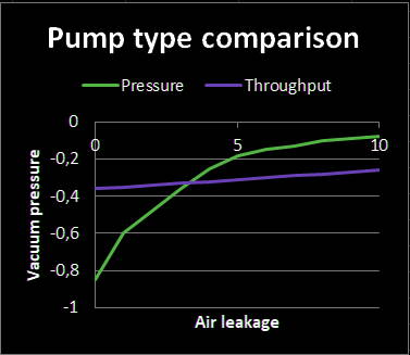
Of course this approximation is very rough and holds true for high-throughput pumps better than for deep vacuum pump types. For the latter, the function looks more like a hyperbolic cosecant (see image below) than a linear graph due to their lower tolerance for leakage air.
We can use the pump’s characteristic curve the following way: When we have a given air volume demanded by our application (like a vacuum table), we can read the reachable pressure difference for this specific pump. This way, you can pre-select a pump type depending on your requirements.
Pump types
 There are a multitude of pump types in the industry. They have different principles of operation and - of course - are suited for different applications. I’ll concentrate on the four types that are most often used for machining.
- Radial blower (High Throughput)
- Sidechannel compressor (High Throughput)
- Piston pump (Deep vacuum)
- rotary vane pump (Deep vacuum)
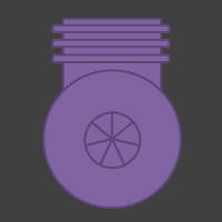
Radial blower
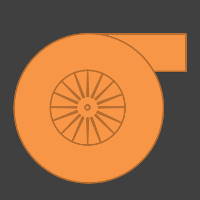 Radial blowers accelerate air between their blades. Air enters the blower at the center of the fan which creates a lower pressure here than in the surrounding air. Then, it is pressed towards the outside due to centrifugal forces as the fan rotates, and is exhausted at the perimeter.
Radial blowers are used for many applications like vacuum cleaners, inflatable castle blowers, forced air delivery for combustion processes, ventilation systems etc. They are simple, come cheap, and are well suited for applications that require very high throughput. The downsides are high noise levels and low pressure differences relative to most other compressor types. However, if you’re working with large surface sheets or porous material, the radial blower e.g. of a forced-air cooled vacuum cleaner motor might be just the right thing for your application.
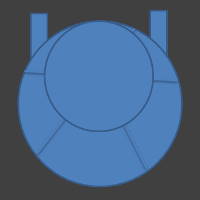
Sidechannel compressor
 Sidechannel compressors combine high capacity with medium pressure difference. They are built single or multi-stage (series circuit) and thus can favour higher capacity or pressure difference according to your needs. Like radial blowers, they interact with the medium only and thus do not have part to part friction that would require frequent maintenance. Like radial blowers, they tolerate vapours and can even be used in dusty environments.
If you want the sidechannel compressor to provide high pressure differences, you’ll have to buy very powerful (thus expensive) drives as their characteristic curves are shallow. Their noise can be efficiently muffled, but they often carry a higher price tag than comparable radial blowers.
In this list, they are “the jack of all trades”. The vacuum they provide can be upgraded to high-enough levels for most applications that don’t require extremely strong clamping and their price is moderate. Cost of operation is determined by the electrical power they consume.
I found this in-depth description of the sidechannel compressor helpful: GutmbH.
Piston pump
 Piston pumps are commonly used in compressors and vacuum pumps alike. They provide deep vacuum levels at a low capacity, don’t use much space in your shop, and are reasonably priced.
On the other hand, their output stream is pulsating and they tend to be noisy. They also cannot handle liquids or vapours and have higher requirements on maintenance than frictionless pumps like sidechannel compressors or radial blowers. I did not find so many notes about their usage for vacuum tables, but that does not mean they’re not suited for this specific application.
Rotary vane pump
 Rotary vane pumps come in two classes again: Dry-running and oil-lubricated.
While dry-running pumps have similar pressure data at higher capacity than piston pumps with the same power rating, oil-lubricated rotary vane pumps can provide a much deeper vacuum level and even higher capacity with the same power rating. On the downside, they commonly need oil warmup and de-gasing cooldown runs, and have a higher maintenance cost due to their oil system.
Rotary vane pumps come in two classes again: Dry-running and oil-lubricated.
While dry-running pumps have similar pressure data at higher capacity than piston pumps with the same power rating, oil-lubricated rotary vane pumps can provide a much deeper vacuum level and even higher capacity with the same power rating. On the downside, they commonly need oil warmup and de-gasing cooldown runs, and have a higher maintenance cost due to their oil system.
Their principle of operation: A motor drives a slotted dish mounted excentrically within the vacuum chamber. In the slots, vanes are placed that can move freely. As the pump’s motor accelerates, the vanes are pressed against the vacuum chamber’s walls, sealing it against the other cavities. This way, compressible media can be transported only.
Rotary vane pumps deliver a continuous flow at low noise levels. The vanes are expendable parts that need replacement from time to time, which is especially true for the dry-running specimen. If you just compare capacity, they usually cost twice to three times as much as sidechannel compressors.
You should get one of theese if you often mill small workpieces at high lateral forces, e.g. mild steel. In this scenario, you can even keep your costs at bay when you’re not cutting through as in that case, leakage air is no issue of yours so you can choose a very low pump capacity.
If you’d like more detail, please find this well-made page (in German) from GutmbH.
Let the workpiece determine your pump
 OK, so you chose the type and size of vacuum table you require for your jobs. Great! Now all you still need is a vacuum source and a way to feed the vacuum into your table.
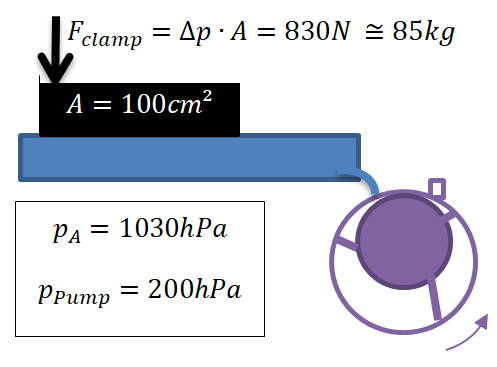
As you can see in the figure, the downforce you get highly depends on the surface area of your workpiece. The smaller your workpiece is, the more pressure difference you require to maintain the same force - with the atmospheric pressure being one limit and the absolute vacuum the other. This makes vacuum tables both a very homogenuous but “weak” clamping method.
Now, what you actually want is to protect your workpiece both from being lifted off the of the machine bed by the tool, at the same time avoiding parallel shifts and rotation of your workpiece while machining. So we have to calculate the downfore created. In a second step, we want to convert that downforce into lateral forces that have to be higher than the maximum lateral force applied by your tool so your workpiece keeps its position.
Downforce
The clamping force to your machine bed is easy to calculate:
\[f_{clamp}= F_N = \Delta p A + F_g\]It is measured in Newton and determined by the pressure difference at the workpiece top/bottom its surface and its weight that gravity forces downwards.
The value you require heavily depends on tool size and geometry, workpiece material, and feed/speed. You’ll require a lot more downforce for a scenario in which you’re milling small workpieces of sturdy materials like HPL with large tool spiral angles and tool diameters at high feeds and low spindle RPM than for cutting plywood sheets with small-diameter straight flute bits at high RPM and low feed rates.
Lateral force
To do the translation of downforce into lateral forces, we’ll introduce the coefficient of static friction \(µ_s\).
Let’s assume you use a sheet of rubber between a metal workpiece and your vacuum table. We further assume a coefficient of static friction µs = 0.7 that I found online which seems really conservative for multiple reasons: First, it doesn’t take surface roughness of both rubber and metal into account, and, more importantly, we’re pressing the workpiece into the rubber which yields a form-fit bonding that increases breakaway force a lot.
Anyways, all you need to do here is to take your downforce calculated earlier and multiply it with this factor:
\[F_s = F_N µ_s\]As you can see, there are two things you can manipulate with the same linear weighing: The material pairing of workpiece surface and machine table determine the coefficient, and the downforce created by your pump.
Rotation
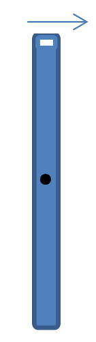 This calculation becomes a bit more tricky. Interestingly, you’ll require less force to rotate a workpiece out of position than to parallel-shift it away. This is why:
When you rotate, say, your mobile phone on your desk around its center (touching it at its top-right corner), not all imaginable points on that phone have to move the same distance. Points closer to the center of rotation will have to move a shorter distance for the same angle of rotation than points at the tip of the phone. For a parallel shift, however, every imaginary point had to move the same distance.
This pheonomenon seems independent of the object’s shape once you compare travel of the outermost point of that object in relation to its center of rotation.
For vacuum clamping, worst-case workpiece and job combination is long, sleek workpieces that need a slot to be milled orthogonally to its longest dimension at the outer edge, creating the highest torque that might lead to rotation combined with little surface available for vacuum clamping.
Best-case of course are round or square workpieces where you cut close to their geometrical center.
Which pump should you buy?
Ok, let’s sum it up:
It’s always a combination of workpiece material (easy/hard to mill, low/high static coefficient of friction), minimum workpiece size (the bigger, the easier it becomes to generate high clamping forces), leakage air tolerance (porous surfaces, cutting all the way through), vacuum table type and size, and milling parameters that determine which pump to buy.
You should collect some experience before buying a vacuum clamping solution: What is your typical workpiece size and material? Do you often do cutouts? Do you require quick execution that exposes your parts to high forces?
Some recommended combinations
- Aluminium, very small workpieces, not cutting through: Low capacity piston or rotary vane pump, grid vacuum table
- Wood and MDF, large workpieces, cutting through a lot: radial blower or single stage sidechain compressor, porous surface table
- HPL, small workpieces, cutting through: High capacity rotary vane pump or dual stage sidechain compressor, hole grid table, optimized CAM strategies for “late cut-throughs” at low depth increment
What pump I chose
I ordered a relatively large table (730 x 655 mm) with 0.5mm holes arranged in a 10mm grid. As I’m still testing a lot of different materials for prototyping purposes, my workpieces never look alike or have similar sizes. That’s why I had to swallow the pill of spending a lot of money on a pretty capable pump that would both do high throughput for bigger wooden sheets that I’d create cut-throughs in and deep vacuum levels for small aluminium workpieces.
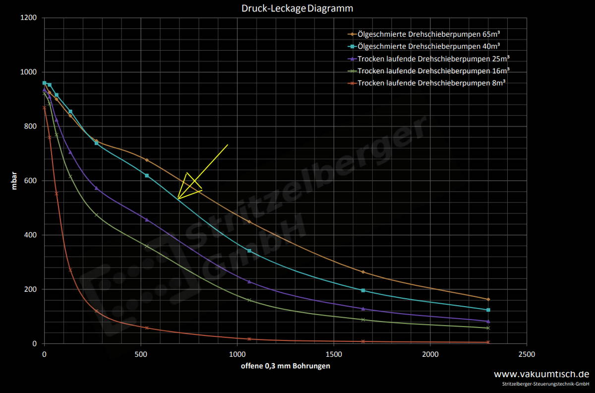
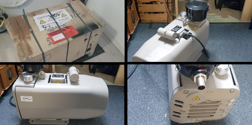
The pump I chose is a dry-running vane-type vacuum pump with a capacity of 40m³/h and a maximum pressure difference of 880mBar. Its air leakage vs. pressure diagram should look similar to the marked characteristic in the plot above. It weighs approximately 40kg and uses a 3-phase induction motor with a nominal power of 1.3kW.
I am using a version where the motor is operated on a single-phase with help of a capacitor due to the fact that I do not have a three-phase outlet available. I also added a motor circuit breaker to help protect the machine against overload and overcurrent.
Is it loud?
It depends on how you define loud, of course. You can compare its 68dB(A) noise level - measured at a distance of 1 meter - with a typical vacuum cleaner, just that it sounds pretty different. When the CNC machine operates, e.g. running through material with a fairly big endmill, it is still quiet and you won’t realize the pump is on.
I even made a short video for you to view and hear for yourself:
Rotary Vane Vacuum Pump - demonstration