CNC Vacuum Table
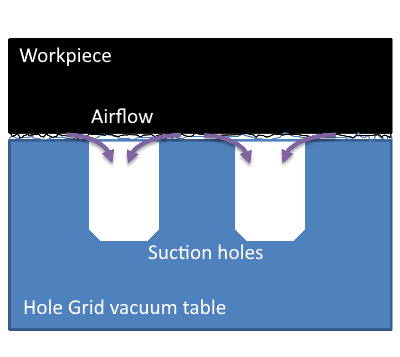
 Let’s assume you clicked this article on purpose and didn’t just “surf the internet”. So you already know what a vacuum table is (If not, continue reading here). Its principle of operation is depicted in the figure for your reference. You probably also know there are multiple types of tables serving different purposes. And you maybe even know that you want one.
Great! This article both describes my journey towards acquiring this piece of tech and also will try to help you select the right one. Let’s start with a little interview.
Why do you want a vacuum table?
This is the most important question.
- 🤩 Do you want it because it’s expensive and looks great?
- 😪 Or because you’re tired of re-adjusting clamps?
- 😖 Or because you broke a lot of endmills running through the former by accident?
- 😨 Or rather because you experienced that workpieces tend to learn how to fly when the adhesive force of your tape is just not high enough?
- 😎 Perhaps because you`re going professional and you want to cut preparation and production time?
- 😕 Or maybe because the work results are not as good as they could (or should) be?
My Reasons: Quality and Speed
I’d go for the latter. I have the following issues I hope a vacuum table can fix:
- When engraving coated materials (Dibond, HPL etc.), slight Z0 surface height differences ruin the work, especially on bigger workpieces
- Cutouts from a bigger sheet have to have taps to keep them from slinging away. These taps are cut away later but are still visible on the end product.
- When I don’t want to use taps, I have to leave an onion skin at the lower layer. With wood, this skin has to be thicker and I need a second job for chamfering which adds time expenditure.
- Some sheets (especially wood) are concave. Thus, when trying to go all the way through, some parts are fine and others are not fully cut.
- My machine suffers from vibrations, especially when using 2-flute wood roughers and high Z+ depth per pass at aggressive feeds. This might be because I use just a couple of clamps to save time and to keep travel paths clear.
Which type of table do you need?
Ok, you know why you want one, now we should find out which type is the correct one for your jobs. Note that vacuum tables are most suitable when you’re milling not too flexible sheet material as the table’s clamping force depends on the surface that is in touch with it.
There are three families of vacuum tables:
- Grid tables
- Hole grid tables
- Porous surface tables
Grid tables
Grid tables have a single (and often centrally placed) suction hole. Their vaccuum area is defined by a (foam) rubber band that can be placed on the grid within the outline of the workpiece. As the rubber band is compressed by the workpiece’s downforce created by the vacuum, the seal is airtight and just very few leakage air has to be evacuated. That’s why they have low requirements on the vacuum pump’s required capacity. They can also be used to clamp materials with rough surfaces due to the rubber band, e.g. saw-cut wood. Grid tables’ designs are often simple and thus affordable.
Altough they really shine here, there are two possibly vital disadvantages: First, when you’re doing singletons, you’ll have to place the rubber band anew for each workpiece. So your XY Zero changes from part to part as most often the workpiece has to be placed centrally on the table. More sophisticated grid tables may have multiple suction holes, and the active one can be selected by the user. They may even offer fences and excenter stops to reduce set-up time. Still, you might not be able to cut any form you like as your limit is the grid.
Second and more important, you run into issues once your part has to be cut “through”. This will immediately make the vacuum collapse and the pump will be overwhelmed with leakage unless you take precautions (build adapter plates or underlay fences etc.)
In short:
- Grid tables work very well if you don’t cut through your workpieces.
- Grid tables have lower requirements on the vacuum pump and can even hold parts with rough or slightly uneven surfaces.
- Grid tables are cost effective but may require additional care when zeroing in workpieces with different dimensions.
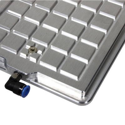
Hole grid tables
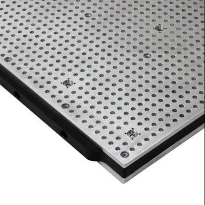
Hole grid tables have - as the name suggests - blind holes that are aligned on a grid. Within these holes, there’s a tiny suction hole that’s size matches the material’s properties you’re machining predominantly - tiny little holes for smooth or polished surfaces like face milled metal, and still tiny but bigger ones e.g. for hard wood and other materials that may have higher air leakages. They often have switchable vacuum chambers below these holes so that the area of where the vacuum is applied can be changed. Uncovered area around the workpiece can be covered with a foil to raise vacuum forces and efficiency. These tables often consist of multiple parts, e.g. a bottom layer for mounting to the machine bed, a middle layer to embed evacuation ducts and the top layer carrying the hole grid.
These tables can clamp workpiece of any shape that have flat bottom surfaces. When your workpieces are really small, of course, the clamping force will diminish - that’s physics. The small suction hole allows for through-cuts: Affected holes do loose their capability to hold the workpiece in place on one hand; but nearby holes on the grid are merely affected as air leakage is limited by the “lost” suction hole’s diameter even at high pressure differences. Aligning the workpiece is even simpler with hole grid tables as their grid’s holes can be used to hold locator pins that build a fence.
Their disadvantages: These tables tend to be more expensive as their design is more complex. They often have multiple vacuum circuits and thus require more connections to your vacuum infrastructure (that have to be kept leak-free). Their tolerance of leakage air and lateral inflow means that your vacuum pump requires to have a higher capacity.
In short:
- Hole grid tables support any sheet shape as long as its surface is flat and big enough to meet your clamping requirements.
- Hole grid tables tolerate through-cuts at the cost of higher requirements on pump capacity.
- Hole grid tables make workpiece alignment a cake walk.
- Hole grid tables are complex and often expensive.
Porous surface tables

These special kind of tables do not need holes or channels on their surface at all - their top surface, instead, is air-permeable. I’ve seen specimen where the top layer is made of MDF so actually it’s not a big problem if you accidentally got Z0 wrong - just place a new sheet of MDF on top and off you go again.
The tables are lightweight and - with a lot of knowledge about materials science and thin-wall milling - relatively easy to construct as a DIY project - many examples are out there on the internet. They work best with a high-volume blower and thus often do not support large pressure differences - so as long as your workpieces are not tiny, that’s not an issue. The tables are suitable for cutting all the way through as well. They are cheap to buy and to upgrade with additional features, and a vacuum cleaner with forced cooling might already be enough to power it up.
The downsides: Might be subject to vibrations due to their low weight, best not to be operated with cooling liquids, unfavorable static friction coefficient with most pairing materials due to MDF (thus more surface needed to protect from slipping).
In short:
- Porous surface tables are cheaper to have and to operate.
- Porous surface tables are well suited for big workpieces and materials that don’t require cooling liquids.
- Porous surface tables may not be perfect for high precision milling.
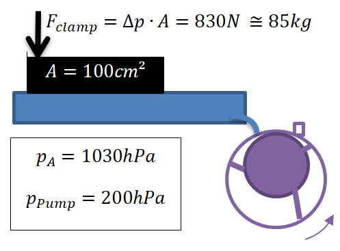
What all these types have in common
 Common to all these types is, that the downforce can safely be calculated the same way for a given vacuum pressure applied to your workpiece (not necessarily identical with what you see on your gauge!). No matter if you have a grid, a hole grid table or a porous surface table, you can always calculate the full surface of your workpiece (and not just the sum of holes’ area within the workpiece’s outer bounds). This is because microscopic surface irregularities of both table and workpiece material allow a lateral airflow into the suction area of your table, making pressure differences between atmosphere and vacuum pump side homogenous.
On the other hand, this is also true for your workpiece’s outline, so there will always be a little leakage air in your system with the side effect that clamping force deteriorates the more you approach the peripheral zone.
That said, cutting all the way through your material will create extra peripheral zones that can, when situated too close to each other, even have zero clamping force left.
What else do you need?
Well, there’s a couple of things you do require. A vacuum pump, for instance, that supplies your table. But you’re in luck, I wrote an entire post on that topic as well. But there’s more, actually:
- Fasteners, washers, nuts to attach the table to your machine bed
- A vacuum manifold that may allow you to select chambers within your table, preferably providing a vacuum gauge to check pressure levels
- Vacuum hose(s) to connect the table to your manifold
- Another vacuum hose that connects the manifold to your pump
- A pump motor switch and motor circuit breaker
- Vacuum fleece or rubber mat (hole grid tables only)
- Vacuum gasket thread (grid tables only)
- porous spoilboard (porous tables only)
Conclusion
All in all, it will cost you a lot of your time and money to get and setup a vacuum table. So you should have a couple of good arguments to go through that effort. If so, chances are high you’ll be rewarded with quicker execution, better quality, and shorter job setup times.
My selection
I exclusively work with sheet material. I process wood, high pressure laminates, acrylic, MDF boards, and often have to cut out parts from a bigger sheet or use nesting for many different parts. This is why a grid table wouldn’t work for me very well.
Due to the vibration issues I have with my current setup lacking enough weight and the fact that a ready-made vacuum table didn’t exist for the dimensions of my machine, I didn’t choose a porous surface table either. This would have been the most cost-effective solution, though.
 Instead, I contacted a vacuum table manufacturer to buy a couple of small hole-grid tables that I could individually switch on and off depending on workpiece size and pressure that I’d require for secure clamping. Well. I was told that a much simpler and better solution would be to buy one of their even heavier aluminium tables. Less worrying to get multiple tables supplied with airtight suction ducts, valves, connectors. Not having to access both sides of the milling machine with ducts. Not having to adjust the tables to sit together tightly or face mill for a level surface. And by the way, they’d create a customized design so it would perfectly fit my machine…
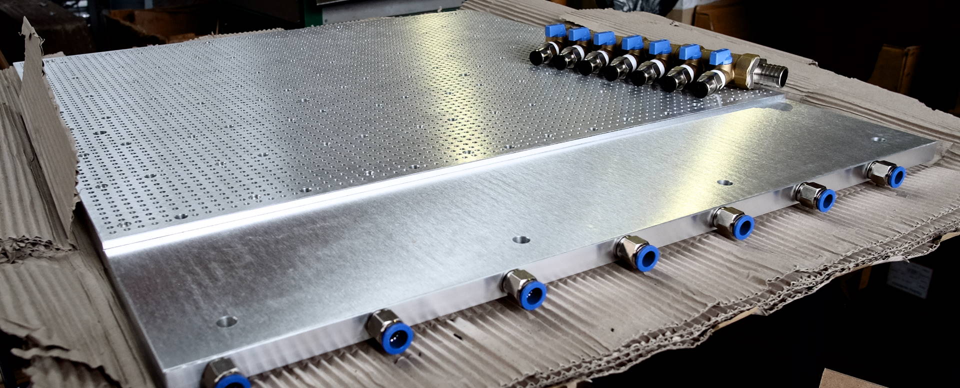
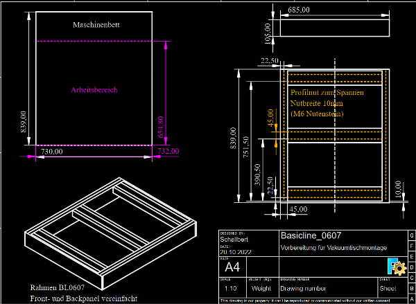
What can I say. I scraped money together for this much more elegant solution. I made a drawing of my machine bed. Just a couple of days later I got a sketch back with an initial design (this one is still missing additional holes for clamping vises, and the grid is less dense to keep processing speed high). I gave my OK for production.
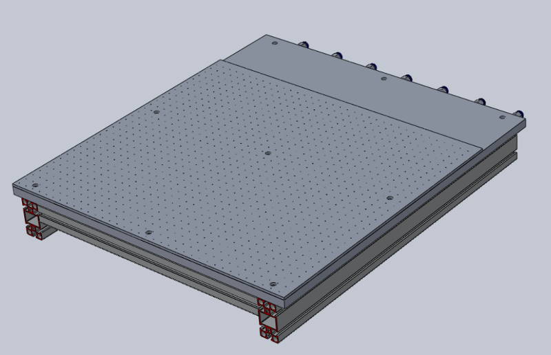
Table delivered
The manufacturer is located not too far from where I’m at home. So I went there and collected it myself. When I had unmounted my old spoilboard, I thought it would be a good idea to have some heavy foam acoustic absorption panels placed in the machine frame to dampen noise and resonation from below the table.
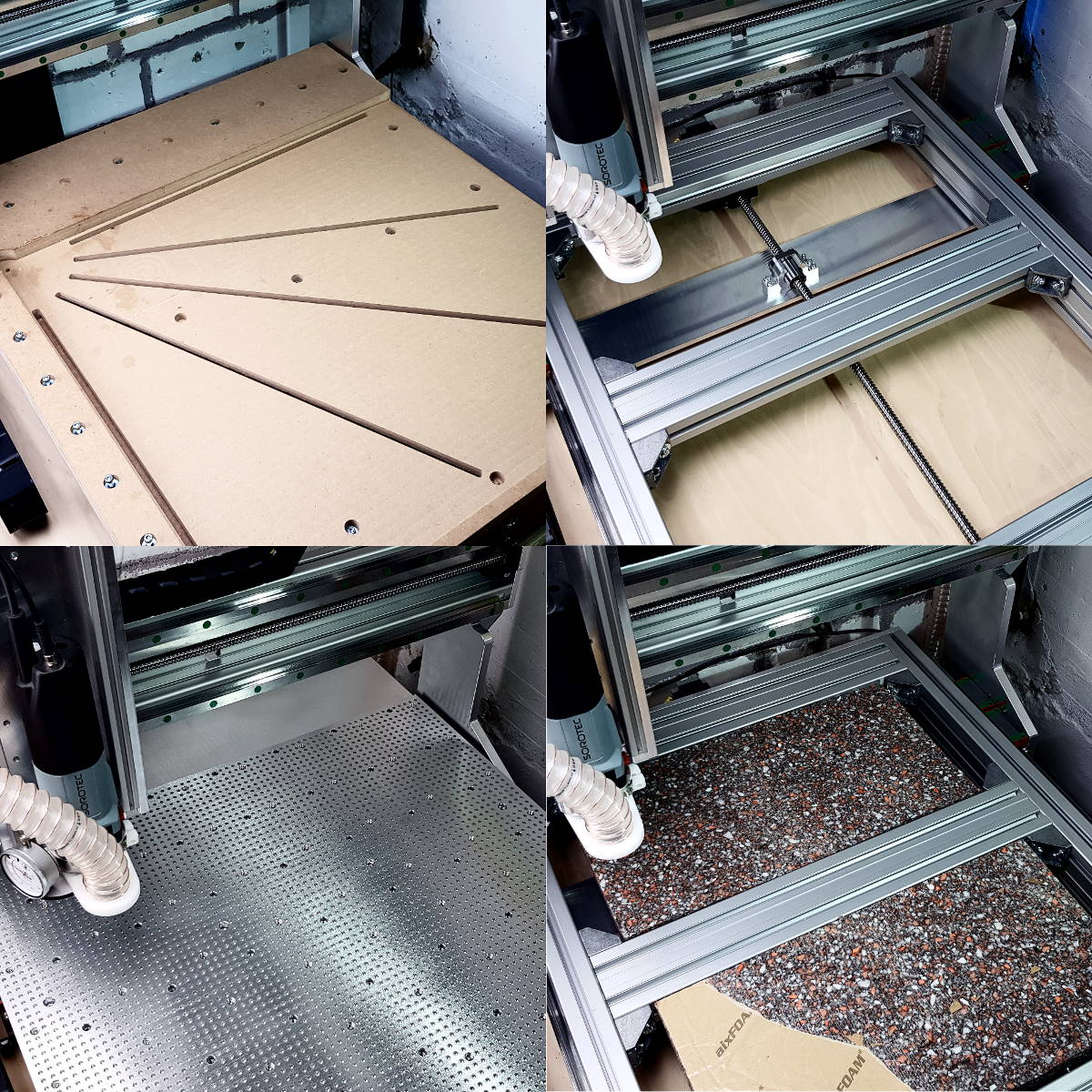
Only afterwards, I bolted the new vacuum table to my machine with help of M6 fasteners and hammernuts. After that it took me multiple hours to get a more or less even surface. As the machine frame’s tolerance is relatively high, I initially had deviations of 3/10mm over the vacuum table’s surface 😓. With the help of some paper and thin cardbord, I was able to smoothen out the roughest dips, but I could still measure a deviation of 15/100mm.
CNC Z-axis bed leveling check
To get to an optimal solution, there would be three options:
- Surface milling of the whole table
- Unmounting the table, adding thin plastic foil where needed, remounting, adding additional foil/paper where needed…
- Unmounting the table, loosen the machine frame and get to the root: the frame’s sides are rotated towards the inner just a tiny bit, and the front cross-beam seems to be bent upwards just a little, so it should be lowered by less than 1/10mm.
For the time being, any of these options seemed too much work as I don’t know yet if I need it to be that exact. So I continued by connecting the vacuum hoses.
Connecting the manifold
While happily cutting the hoses that would connect the vacuum table to the manifold, I thought “Wait a second - wouldn’t it be better to have the 9mm hoses as short as possible and rather use a longer 19mm pump connector hose for less flow resistance?” I stopped work and did some calculations:
My table has ~4900 holes of 0.5mm in diameter. Its combined cross section is \(A_{table}=962mm²\), which is equivalent to a hole with 35mm in diameter (differences in flow resistance ignored).
The seven connecting hoses have a diameter of 9mm. Together, their surface is just \(A_{hose}=445mm²\), equivalent single diameter of 24mm which is less than half than the table’s flow section.
For the pump hose and its diameter of 18mm it gets even worse: \(A_{pump}=254mm\) is less than 30% of the table’s capacity.
So when I assume an even air leakage over the seven chambers of my table, it makes most sense to have the pump hose as short as possible as the flow speed is highest here and so are the losses. For a scenario where just one of the table’s section is active and there’s a lot of leakage, obviously the 9mm hose should be as short as possible.
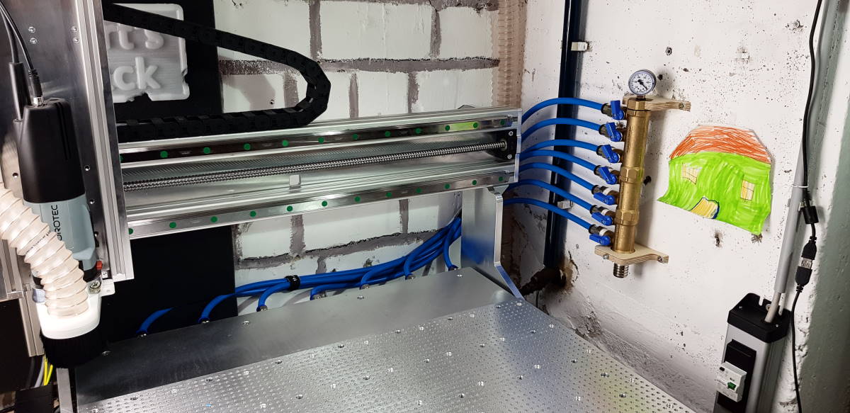
I decided instead to never allow full leakage so I could keep my preferred, comfortable location of where the manifold is mounted and just completed the wiring. 😉 By the way, the first part I manufactured on the new table was the holder for the manifold you can see in the image below.