Dibond Tests
Note: The engravings I disuss in this article are relatively fine. Font size is between 3mm and 6mm, and workpiece size is 80x80mm. Viewed at a distance of an ell or more, the quality issues are not apparent and the overall impression is quite good. Still, I wanted to improve.
Further quality tuning on Dibond
After I got mediocre results with my previous milling project, I decided to do some more test runs in Dibond. Before I started those, I noted down possible causes for rough cutting edges that I saw earlier.
Then, I’ll try to rule out noise factors to track down root causes, and in a further step I will do my best to eliminate most of the issues.
Possible causes for poor quality
- Worn-out or dull cutter
- Cutter geometry
- Improper Feed / Speed parameters
- Climb milling vs. conventional milling
- Too shallow engrave depth
- Too high depth per pass on the Engrave cutter
- Machine vibrations on portal acceleration and/or deceleration, especially on Y-axis
- Router motor mount not stiff enough
- Imbalanced cutter / collet
Cutter inspection
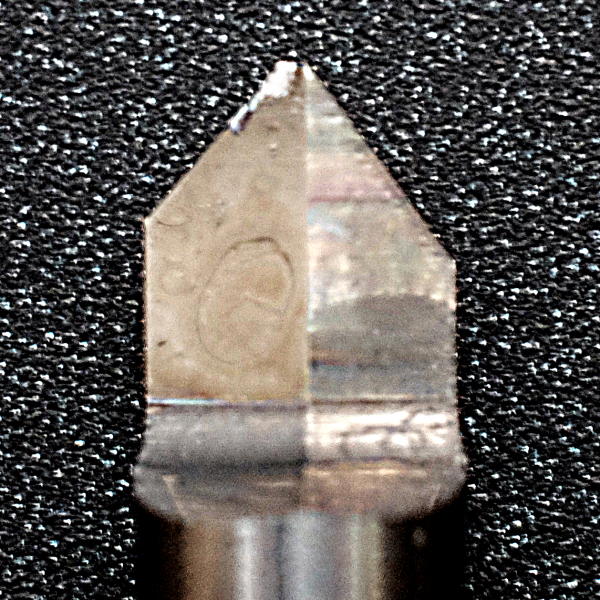
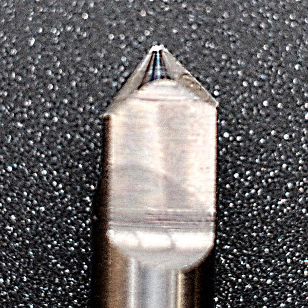
I’m not an expert on cutters, but I cannot imagine that a carbide bit is worn out after half an hour of cutting through 0.3mmthick AlMg1 which is the harder compound of Dibond composite material. Also, the cutting edge seems to be in a good shape. The only thing I noticed was that there seems to be a thin layer of Aluminium sticking to the tip of the bit. Maybe this affects cut quality?
Carefully, I removed the aluminium residues with a trimming knife and minimal sanding. As good as new!
Cutter geometry
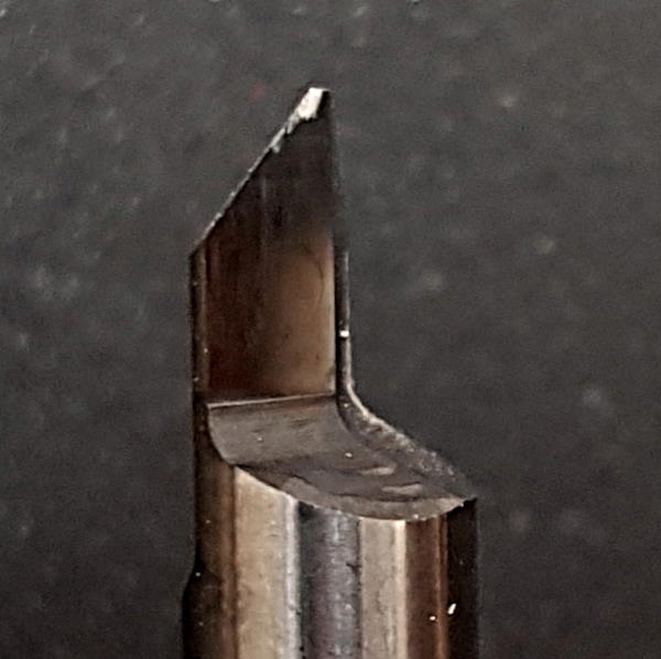
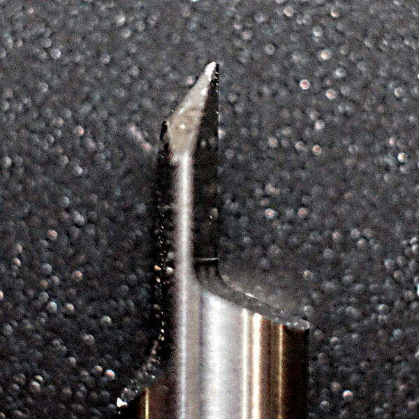
The cutters I’m using for this test do not have chip flutes to guide shavings away from the place of cut. There are others on the market which do provide one and I wonder if it makes a difference. Maybe a spiral flute could improve quality of cut?
Background behind that thesis is that for cutting letters, my CAM won’t use the defined dive ramp but plunges straight into the material. When you have a closer look at the images below, you might even see marks in the clearcoat around the place where the cutter hit Z0, shearing the surface away but not yet expediting the chip away from the cut.
On the other side, a spiral flute will try to pull the aluminium layer upwards. As it is “only” thermally bonded to the polyethylene core, adhesive force might be too low, especially with fine engravings or letters like “e, a, o, R, B…”
Summary: Buy spiral flute engrave cutters, try them, and document the results 😅
Improper Speed / Feed parameters
I double-checked required spindle RPM for my engrave cutter which is single-flute. I again got a value higher than my maximum speed of 24000RPM, so I can confirm to use my motor’s maximum speed with that bit.
To try out other feed rates, I created a quick 2D design in my CAD and had my CAM run it in different feeds: F600mm/min, F800mm/min, and F1000mm/min.
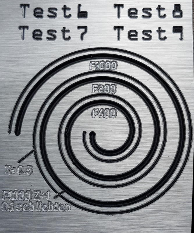
There are a lot of things that we can observe here:
- Look at the labels for the different feed rates. The font is so small, that the engrave cutter won’t even fully cut through the upper Aluminium layer. It rather “mashes” the aluminium into the polyethylene layer below, and squeezes the aluminium sideways.
- Although I change the feed rates by as much as 20% per spiral turn, quality of cut remains the same. This confirms that for my
6mm 0.5tip 90°cutter in Dibond, a feed rate ofF1000mm/minis fine. - It is clear to see that the “outer” edges of the engrave operation are rough. I can feel this when I stroke the workpiece with my finger.
- The “inner” edges of the engravings are really smooth, though. They gleam in contrary to their matte counterparts.
- The black, inner parts of the spiral are shaped very even and without cutter marks or a lot of remaining chips.
- The capital “T” of the word test runs looks a bit strange as there are vertical marks. Let’s come to this later.
Summary: Speed and feed parameters are fine and don’t seem to be the culprit for poor machining quality in this case.
Climb milling vs. conventional milling
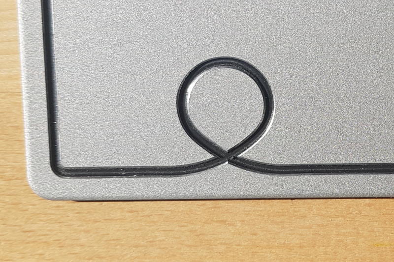
To get a clear view on the effects of milling strategy, let’s take a detailed look at the spiral.
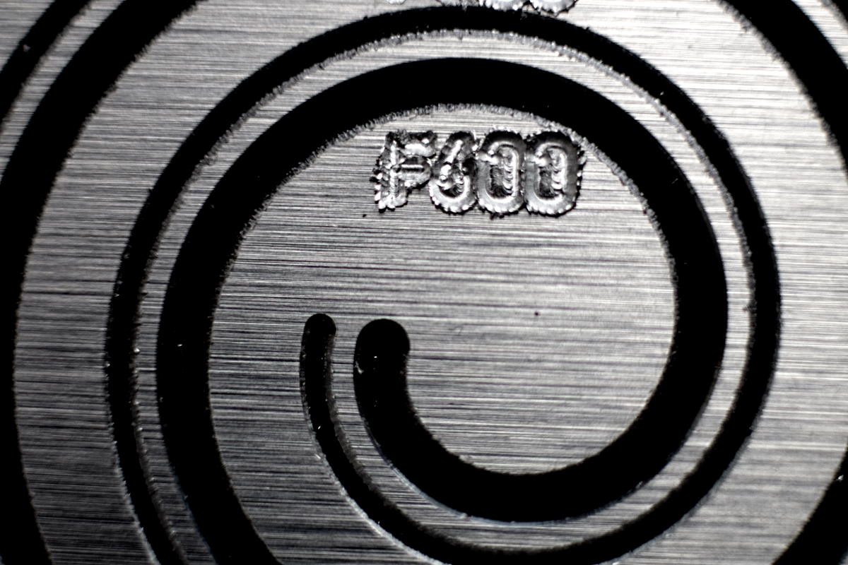
It is easy to see that the outer cut has very clean edges while the inner one has not. The spiral has been milled outwards to inwards, and the spindle turns clockwise. The groove was cut in a single pass for the narrower line, and with a smoothing increment of Z-0.1mm for the wider one.
This means that conventional milling has been applied to the outer edge of the groove, and the inner edge was machined with climb milling, i.e. the cutter was moving in the direction of cut and not against it.
Summary: Although climb milling is preferred on a CNC for various reasons, this is not true for aluminium composite materials like Dibond. Here, conventional milling is the strategy to choose if you want clean chamfers.
Too shallow engrave depth
Summary: As the images above show, it is a problem if the aluminium layer is not fully broken through. In some follow-up experiments I tested a minimum viable engrave depth and ended up with a value of ~150% of the aluminium layer’s strength, in my case that is 0.45mm.
Note that this constraint might only be valid for V-cutters that don’t feature spiral cuts or cutter flutes.
Too high engrave depth
This was a guess that came up when looking at the images from my previous experiment with Dibond. To compare, I created two spiral engrave paths with different depths of Z-0.5mm and Z-1.0mm. While the former wouldn’t make any difference when I add another pass for smoothing, it makes the latter engrave look a little more clean.
Summary: For deeper engraves, smoothing runs are helpful but not a must. Instead, a much bigger lever to improve quality is to use conventional milling only.
Machine vibrations
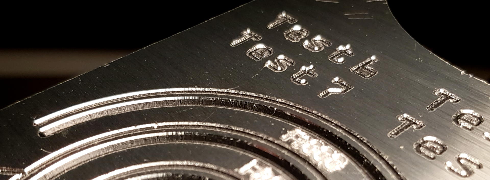
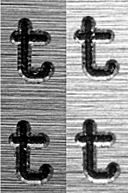
Remember the test texts carrying strange marks? At the beginning I thought this was due to the brushed-look surface: It is not actually brushed but imprinted under high pressure using rollers. But when I had a closer look, another assumption came to my mind: Machine vibrations.
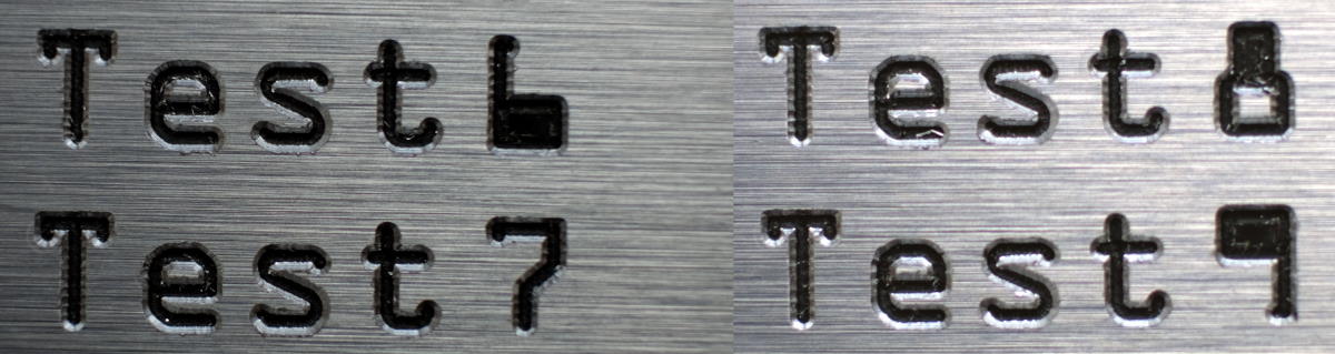
The texts have been made with different feeds, where 6 indicates 600mm/min and so on. Below on the right I have prepared a second image that has an extra zoom into the “t”s for better comparison of the feed rates. Actually, the quicker engrave settings look better than the slower ones.
 I have been excercising the limits of my machine a lot in the past half a year. I came up with pretty high values on acceleration and maximum velocity which I verified the machine was capable to work with.
“Unusually high” is actually what the manufacturer of my controller software said when I contacted their support with an unrelated issue about a warning message
I have been excercising the limits of my machine a lot in the past half a year. I came up with pretty high values on acceleration and maximum velocity which I verified the machine was capable to work with.
“Unusually high” is actually what the manufacturer of my controller software said when I contacted their support with an unrelated issue about a warning message Velocity was higher than max! a couple of weeks ago.
That said, to verify my hypothesis I created yet another test sample in CAD and CAM where I’d only carve Test texts and straight lines with sharp corners so that the machine has to accelerate and decelerate to full carve speed and back to zero more often.
This time I’d keep the feedrate constant at f1000mm/min but change the machine’s acceleration values to see whether the acceleration unsettles the machine’s portal system in a way that shakes are propagated to the tool tip.
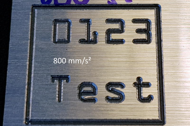
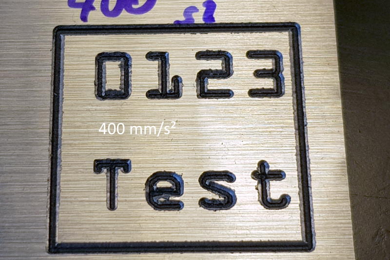
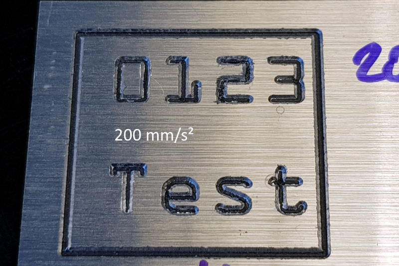
You can see that the vertical marks become less visible on lower acceleration settings. As I had to reset the machine after each parameter change, I must re-measure Z0 height everytime. On the lowest acceleration setting, I probably had a grain of dust below the sensor as the depth of cut is visibly less than on the other two test samples which deteriorates the engrave quality.
Question: “Did the machine reach target speed at all?” Text height is s0=6mm, so for example at a=800mm/s², the machine takes t=f/a=20ms to accelerate to its target feed rate. Travelling a distance of s=a/2*t^2=0.17mm while accelerating, the machine will run s1=6-2*0.17=5.66mm with target speed within the vertical stem of letter t. This proves that the machine actually gets to run its targeted feedrate. Basic kinematic laws come in handy when working with CNC machines from time to time.
Summary: Make sure your machine runs in a fine-tuned parameter envelope relative to its size, stiffness, weight, and control variables so you avoid judder.
Router motor mount
I know this could be a problem from my past experiments where at some point I overloaded my machine. But for engraving, the spindle runs at just 20% of maximum load.
Summary: This is not an issue here.
Imbalanced cutter / collet
Summary: If this was the case, I would have either expected strange sounds or vibrations emanating from my machine. Maybe also edges with irregular shapes or torn chips could be a side effect. Neither of that is the case, so I’d exclude this noise factor here.
Process and machine updates
Here’s what I actually did:
- Inspect and clean cutters after usage
- Try to avoid climb milling in dibond. Rather have the engrave path a little wider, and have both edges of the engrave cut conventionally.
- Add a smoothing run when engrave depth exceeds
Z-0.6mm. - Reduce machine’s maximum acceleration values to minimize cutter marks.
- Prepare a tryout CAD file to experiment with for optimal feeds and speeds when trying new materials.
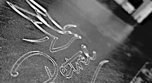
See for yourself how the quality improved after applying all these changes.