Halftones on Dibond
Lately, I rediscovered Dibond (aluminium sandwich panel) as a material for machining. I use it less and less for environmental reasons - composite materials are not something I consider particularly sustainable or recyclable. Nevertheless, the beautiful surfaces always have a certain attraction for me. Now then - let’s get down to business!
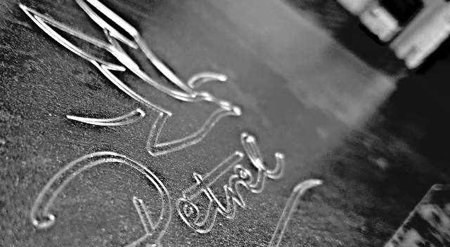
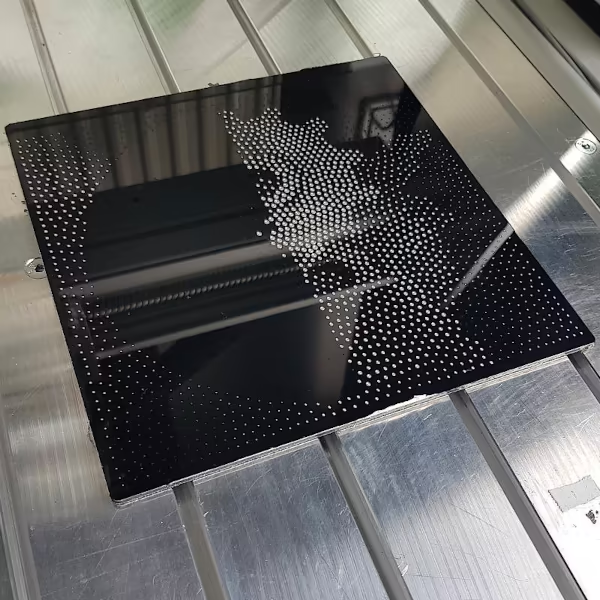
Blog logo as a point cloud
I was now able to throw an image created by Stipplegen onto the milling machine. To do this I had to solve a problem that was still present in the previous post Milling grayscale images with the CNC: In my most frequently used CAM tool, milling paths for point-based halftone images can hardly be created because each of the over 2200 points would have to be individually assigned a milling operation.
CADasCAM, on the other hand, allows you to add entire groups of elements to one and the same milling action. Now I asked myself which milling cutter I should best work with in Dibond, since I only have a very thin covering layer available.
Simulation radius cutter
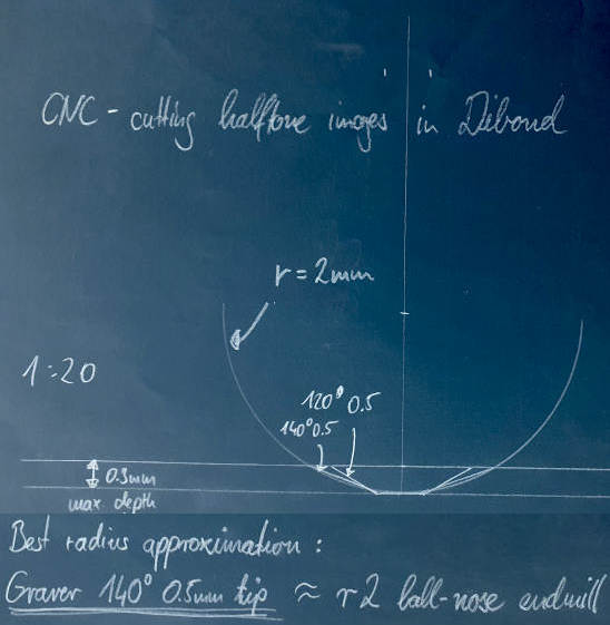 I decided on a radius cutter with a half-round head. However, the CAM has no calculation rule for this, so it cannot be selected without further ado. After consulting the manufacturer, the idea came up to simulate the radius cutter for the CAM using a V-cut with a flattened tip, but actually using the ball head on the milling machine.
In order to get suitable values here, I made a few drawings. The table below contains approximate values for the case where the immersion depth does not exceed 0.3mm. I was now able to carry out the path calculation in the CAM and even adhere to a depth limit of 0.22mm. The flattest areas have an engraving depth of just 0.10mm.
When calculating the path, it is important to note that the retraction heights should be as low as possible. Then the Z-axis of the machines does not have to move up so far for every point. I consider a value of 0.5mm to be appropriate.
| Radius milling cutter | Simulation by V-Cut |
|---|---|
| r=3mm | 140°, 1.0mm flattening |
| r=2mm | 140°, 0.5mm flattening |
Milling process
The motif size for the engraving is 180x180mm and I mill with the following values: Radius cutter 2s r3 6mm, S20000, F1800. I pierce the protective film of the Dibond plate, the thickness of which I do not compensate for. I use a small amount of lubricant to improve quality of cut. After just 11 minutes, the milling process is finished.
Observations
The motif is much clearer in this attempt. Unfortunately, I still have a clear problem with the surface flatness. For example, the engraving in the middle area on the right is too deep (built-up edge - see video - that’s where the milling machine is at the end), while the engraving depth at the very top right and top center does not seem sufficient.
- The milling machine and milling cutter have no problem with the material at all. The engraving process sounds a bit like working with a box column drill, interrupted by positioning noises from the stepper motors.
- The type of aluminum AlMg1 used for Dibond is soft and chewy. It is not well suitable for machining.
- Milling cutters tend to create built-up edges, which increase cutter radius and worsen the cutting quality.
- The protective film prevents tears and chip edges.
- Applying a little lubricant is a good idea.
- Even on a vacuum table, every speck of dust under the workpiece ruins the milling work. A few hundredths of a millimeter difference in height has a major impact on the point size and leads to distortions.
- The machine bed must be absolutely flat or the machine must have high-quality, active height compensation; e.g. by means of prior surface measurement using an edge finder. My control software even supports the procedure under the name ZheightComp.
Conclusion
- I really like Dibond as a material, but it doesn’t seem to return my affection.
- With my technical means, I can’t produce engravings that are repeatable and of good quality.
- Maybe I should use plastic or wood instead. Or use a laser…
Finally, a short time-lapse video of the milling process.
Halftone on CNC - Part2
Saturn as ASCII art
Halftone images can of course also be created with patterns instead of lines, waves and dots. As an example, I prepared the image of the planet Saturn from Christopher Johnson’s ASCII art for the CNC machine.
CAD/CAM
To get the aspect ratio correct, a font is required in which each character has the same type width. I choose the TrueType font Courier New and adjust the font size and line spacing so that the motif fits on my material and the engraving does not perforate the cover layer.
This forces me to use a 1/8" engraving bit with a 36° tip angle and 0.1mm flattening. I would have preferred a radius cutter here: In soft Dibond, acute-angled endmills cause material to bulge and smear. This leads to unclean lines and a rough surface. However, since the workpiece is very small, the font would be much too wide.
The path calculation shows that I have to choose bold letters on the workpiece, which is only 80x80mm in size, in order to even reach my minimum depth of 0.08mm.
Production
I made the image of Saturn twice: on 80x80mm to test the maximum resolution in the material and on 180x180mm (image below) to check contrast and wider letters.
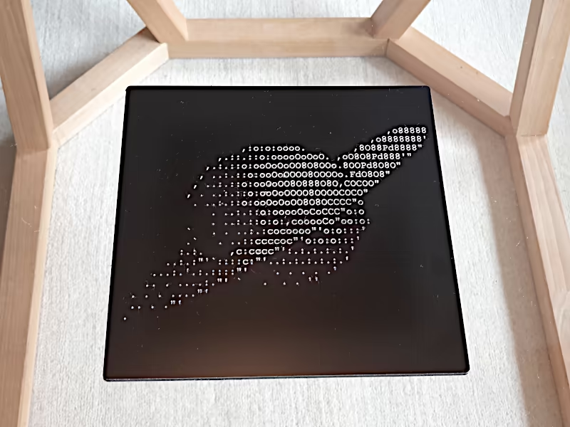
I am happy with the result. The contrast is high and the silver-white surface of the aluminum (oxide) looks really classy on the matt black paint.
Halftone on CNC - Part3
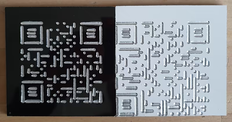
QR codes
While I’m already working with Dibond: I’ll try cutting a few QR codes with a radius bit. This time I’m using different machines.
On the Hobbyline
I engrave in black on the Hobbyline provided to me in overclocked engraving mode. I fix the workpiece with a few dots of double-sided tape. I mill dry. Observations:
- The engraving depth seems to increase with increasing line length (built-up cutting edge, milling cutter smears into the material)
- In some cases the paint surface at the milling edge bulges upwards
- Very dirty milling channels, strong direction dependency
On the Basicline
Here I naturally use my vacuum table and benefit from the much more stable structure. I use a small amount of lubricant. I was curious to see whether the white material still allows sufficient contrast. Observations:
- My QR-codeengrave software must be operated correctly. Otherwise, zero points and size ratios shift, as here. Result: My cell phone does not recognize the QR code 😐
- The much better hold down prevents major differences in milling channel width.
- Nevertheless, you can see the machine’s exit points and sometimes also dragged chips.
- The milling quality is still not satisfactory.
Conclusion
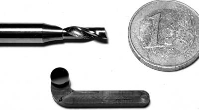 In the future, I will have to treat Dibond in a similar way to acrylic glass: use very sharp endmills that cut the material properly. Ideally, single-flute cutters with a hawk’s beak and corner bevel (soft edges), center-cutting, and a decent twist. E.g. this one (link to vhf). This - I believe - prevents material displacement into the even softer core material and also moves chips upwards in the chip channel so that they cannot stick or get under the milling cutter a second time.
I should also work with rapid feed rates. Then the material does not heat up too much. Using a little lubricant and applying protective film contributes to better milling results. Further processing instructions can be found, for example, in the CNC-aus-Holz forum. It may be worth browsing.