CNC-made greyscale images
Up until now, I have always created images as engravings in solid colors. This allows texts like this one, but also drawings and real images to be produced with high contrast and attractively.
The goal
With solid color representation, many details cannot be reproduced. But now I would like to bring a photo into the material. Ideally, this should happen quickly, without manual rework and with high image quality.
My CAM tool provides a “halftone image” function for this, which I will experiment with below. Here, too, it is unlikely to get good results of the machine straight away. In addition, the creation of such images is very time-consuming.
Therefore, at the end of the article I will give a few tips and tricks that can help you achieve good results more quickly.
A little color knowledge: Rasterization
The problem of wanting to represent an entire color space with only a few available colors is hundreds of years old. While color gradients can be excellently drawn by mixing colors in the analog world and also on the screen using different luminance values of the three color channels in pixels, not every application has a large number of colors available.
Printers, for example1. They usually only have the three basic colors cyan (C) - a shade of turquoise, magenta (M) - a shade of pink, yellow (Y) - yellow and key (K) - usually black - at their disposal. From these they then have to create the illusion of all possible colors, because they cannot mix the pigments due to their high opacity. Otherwise the last color applied would dominate or the color would simply run plain. This results in the need to use dot grid or other rasterization processes.
Halftones (halftone image)
One of these raster processes is called halftone. This involves using colored dots or patterns of different line thicknesses to simulate a color tone, which the eye can no longer resolve from a certain distance and therefore “averages” together with the surrounding free space and possibly other colored dots to form a tone value.
This process is suitable for production using a CNC milling machine, provided that the surface of the workpiece to be processed has a different color than the core material.
There are many different production processes for halftones, in which the arrangement of the dots, lines, pattern shape, etc. can sometimes differ greatly. On the CNC, the engraving material used, the required resolution and the desired tool determine the process, since good quality cannot be achieved with every combination.
Dithering
Dithering is more commonly used for display on screens. Unlike with the halftone process, the strength or size of colored dots or patterns does not vary, but rather the spatial distribution of differently colored dots that are sprinkled into the base color. This creates the impression of a mixed color.
Here, too, there are various generation methods: diffusion, noise, patterns, Floyd-Steinberg algorithm…
Material selection
I’ve tried out a lot here. The best materials are those with a homogeneous composition and a high contrast between the surface and core color. In addition, the layer thickness of the surface material should not be too large, as it has to be completely pierced and very large individual dots are then quickly required. The surface is ideally matt. Silk, metallic or high gloss surfaces create a viewing angle dependency that affects the recognizability of the motif.
In addition, the material should be completely flat to the milling surface, as otherwise the dot size varies undesirably.
Suitable materials 👍
| Core material | Coating | Special feature |
|---|---|---|
| Medium-density fiberboard | Primer + paint | Do not overlap the milling path |
| Aluminum composite material | Paint or film | Mill to a maximum depth of 0.18mm |
| Acrylic glass (PMMA) | Paint or film | Use XT (low thickness tolerance) |
The least effort for me is processing finished painted aluminum composite material. Practically no preparatory or post processing is required here. However, it is important to limit the milling depth to 0.18mm. Otherwise the PU core will be deformed or tear-outs will occur.
Applying a film can be a good solution if you don’t want to spend time applying paint. Unfortunately, I’m not particularly skilled at working with film. I’m constantly creating air bubbles or inclusions of tiny dust particles. After the milling process, the resulting defects in the height profile are clearly visible in the form of holes in the material that are too large. Plus, when cutting through those bubbles, there’s no adhesive force between film and surface material which can lead to film rip-offs.
Unsuitable materials 👎
In my opinion, the materials listed here are not well suitable for creating halftone images. I have uploaded a few pictures of unsuccessful attempts here. Often, one reason for failure is that the image resolution is too high for the material.
| Core material | Coating | Base |
|---|---|---|
| Medium density fiberboard | Veneer | Layer thickness too high |
| Medium density fiberboard | Metal film | Paper core of the metal film is white |
| Aluminum composite material | Metal, brushed | Material “mushy”, poor resolution |
| Aluminum composite material | None, PU core | Aluminum pressed into core, poor resolution |
| Soft aluminum alloys | Paint or film | Aluminum smears, poor resolution |
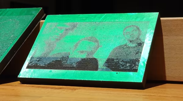 Here I’m experimenting with the pixel density. In the lower area I arranged them too closely so that the coating comes off during milling. On my engraving CNC, such an image on a plate measuring
 15x10cm takes about 15 minutes despite overclocking. The material is not well suited for such high resolutions because of the metallic shine, the risk of tearing, hardly achievable surface adhesion, and the high layer thickness.
Halftone images: Requirements for the CNC
For once, the problem here is not related to holding forces, milling forces or difficulties in holding down. On the contrary, when milling images, low forces are applied and that mostly in Z-direction where the machines have highest stability reserve.
The complexity of the jobs is the problem. The portal has to cover long distances and constantly brake and accelerate along the way. This puts a lot of strain on the power drivers, stepper motors and bearings of the linear spindles.
Waves/strokes/lines
In the segment process, the machine moves across an image line by line. Brightness information is usually transferred via milling depth, so that particularly dark areas produce wider lines when using an engraving cutter. This process is ideal for milling in foam, MDF and acrylic glass. It can also be carried out quite quickly because the machine remains in contact with the material and positioning processes are only required for line jumps.
Dot process
 Here the size of dots is changed so that sometimes larger and sometimes smaller stipples are created in the material.
Halftone images using a dot process require a relatively long time on the machine. What can be done in half an hour with a hobby laser easily takes two hours with a CNC machine of the same size and resolution (here too there are optimization options).
To produce such images, the machine has to move the Z axis extremely often. When milling points, it has to switch between safety height and material engagement once for each “pixel”.
Example: If
400x400points are milled (that would be a pretty poorly resolved image at pixel scale), the machine has to set its Z axis in motion32000times!
Therefore, the safety height should only be a few tenths above the workpiece surface, e.g. 0.5mm. To protect the heavy Y axis, it makes sense to process the image line by line on the X axis using CAM. This way, the Y axis is only moved for line jumps.
A light gantry milling machine with little mass on the Z axis is advantageous here. It should be well lubricated and the axis guides cleaned. At the same time, it doesn’t need to be super stiff as not to oscillate due to the many abrupt movements.
For stepper motors and drivers, these jobs are marathon races. Their temperatures should always be kept under close observation. I recommend not running the machine with halftone images in continuous operation. The axis and portal loads, on the other hand, are negligible: the machine is hardly exposed to any load in the X and Y directions, as it is mostly in contact with the material downwards and only minimally to create conical indentations.
Labyrinth/line segments
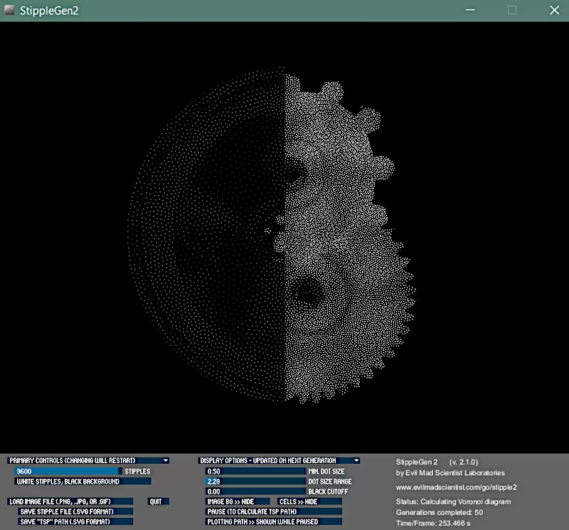
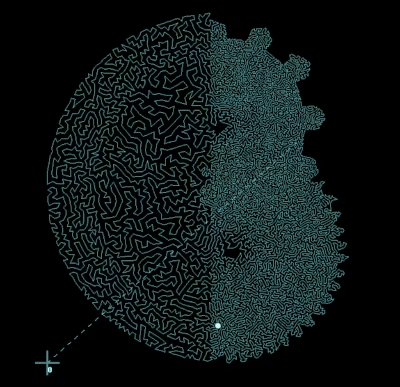 If the entire image is to be covered in just one go, a “travelling salesman problem” (TSP) must first be solved, such as EvilMadScientist’s software Stipplegen2 is capable of. In this process, the density of line segments per area is increased if an area is to appear particularly dark. Such images can be completed quickly on the CNC machine, as they only allow the Z axis to dip once.
The disadvantages of this process are the low achievable resolution (a lot of points are required) and the low contrast, because all lines are the same thickness.
CNC tools
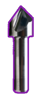 The creation of halftone images is engraving work. It is therefore recommended to use gravers with a
 60° or 90° tip angle and an engraving width of 0-0.5mm.
If the motif is small, an engraving width of 0 may well be chosen. The tip angle should be large if you do not want to or cannot mill deeply or if the “light color” is the core color of the material. This avoids deep shadows that darken the image.
If you are machining painted aluminum composite panels, I can recommend half-round cutters with r<2mm and a very low depth of cut at or below 0.18mm. However, this assumes that the machine bed is face-milled and therefore very evenly aligned.
Manufacturing
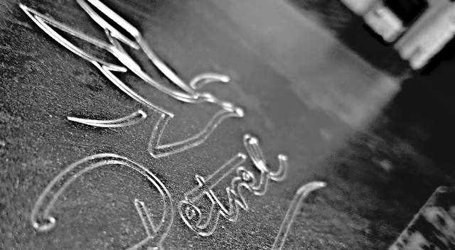
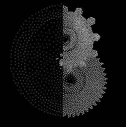
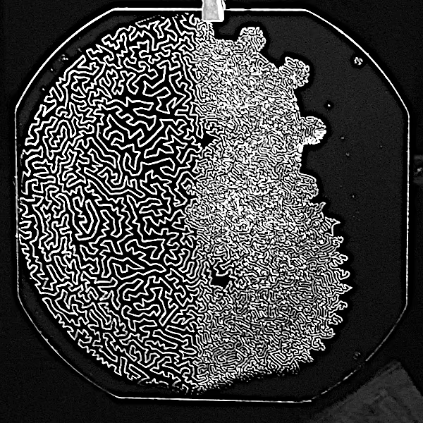 Image: Attempting to engrave my blog logo as a TSP path with 9600 edges on black painted aluminium composite material. I used a
 1/8" 36° graver, 0.1mm engrave width. At the bottom of the image you can see that the material is a little convex and can therefore no longer be reached by the graver.
Image preparation
The image should have a high resolution and be in greyscale. Ideally it should have high contrast and use the entire greyscale spectrum.
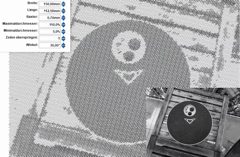
The image is now loaded either into a CAM tool that supports the creation of halftone images - e.g. from Vectric, Estlcam - or into an editing tool that can create point clouds or paths, e.g. Stipplegen2 or Inkscape.
There I always try out a few different settings depending on the material used, desired cutter and image effect. You can often see there whether the image production would work and you can assess whether the resolution is suitable for the material used.
How to get good results
- Prefer large dimensions: The larger the image is chosen, the less noticeable material inhomogeneities and torn-out spots are.
- Allow a large observation distance: The further the image is positioned from the viewer, the sharper the resolution is perceived. Before it eventually appears too small 😆
- Take the angle of incidence of light into account: If the material is half-matte, metallic or even high-gloss, the image quality depends very much on the viewing angle and the distance to the light source. The shinier the material, the smaller the area in which the image can be clearly seen.
- Use homogeneous, non-smearing materials. I have achieved the best results with acrylic glass.
CNC run
There is one thing you need to bring with you here: time. Below are a few video clips from my experiments (time lapse).
Halftone on CNC - Part1
-
Exceptions prove the rule. Of course there are versions of both screens and printers that get around this problem: They use subpixels with additional colors and can thus cover larger color spaces or - as is common in gravure printing (magazines, packaging, etc.) - use a higher number of colors or color mixtures whose tonal values are closer to the required halftones. ↩