
Inrush Current Limiter - Part1
Contents
Electronics knowledge article: Inrush current limiters#
What is it?#
A so-called inrush current is the surge current that flows through a circuit directly after start-up until the circuit has reached its steady state. High inrush currents are often unwanted because they can overload circuit parts reducing their lifetime, create electromagnetic interferences, and cause a short-term voltage drop that may lead to running resets of a controlled device like described here or to other undesired behaviour.
Example#

~100ms, the voltage stabilizes as current flow through the lamp still reduces a bit while the filament slowly reaches steady state temperature.
![[1]](https://commons.wikimedia.org/wiki/File:Lamp_inrush_current.png#file)
Background#
The bulb’s filament acts like a positive temerature coefficient (PTC) resistor: It has a very low resistance at room temperature and a much higher resistance at its normal operating temperature of ~3300K.
A small experiment proves this:
If I take a 116W halogen incandescent light bulb, its resistance in “steady state” at 230V is around \(R_{steady} = \frac{U^2}{P} = 456{Ohm}\).
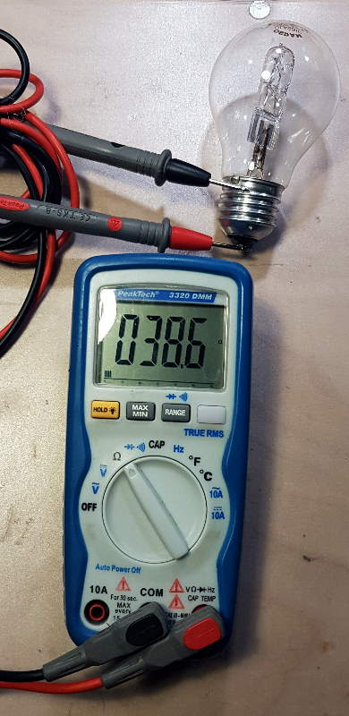
When I take its resistance using a multimeter in the switched-off state, I measure \(R_{off} = 38.6{Ohm}\).
While this lamp normally consumes \(I_{steady} = 0.5A\) of current, at the moment I switch it on, it will draw about \(I_{inrush} = 6A\) which is 12 times as much!
Inrush current limiter circuits#
Inrush current limiter circuits are quite often used in devices with big inductive or capacitive loads. Examples are transformers, motors (inductive), power amplifiers, switching power suply (capacitive) etc.
There are several types of inrush current limiters (TI application note) with varying complexity.
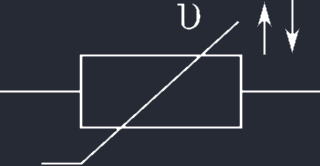
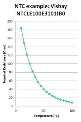
Negative temperature coefficient resistor (NTC) / thermistor#
Limiter using a Start-up relay#
This circuit avoids the disadvantages of additional series resistance to a load by adding a power resistor and a relay. It is typically used in high-power DC supplies or sensitive devices like amplifiers.
The relay contact is normally open and wired in parallel to the power resistor which has a value of typically 1...22Ohm depending on the load. Behind this, the load is connected which causes the inrush current to occur. For this example, I take a car’s light bulb as load. When switching the device on, the resistor will limit circuit current and voltage on the load side will gradually increase. Once the voltage at the NPN BC337 transistor’s base is high enough, it will switch on, allowing current to flow through the relay coil which then short-circuits the power resistor so that the load can unleash its full power potential.
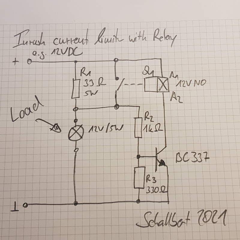
Calculation of R2, R3 depends on the steady state voltage you get behind R1 when relay coil is off, the characteristics of the transistor you choose, and the current the relay needs to work properly. In the example I choseR2 = 1kOhm as I need the transistor to safely drive ~40mA to the relay, so I couldn’t select any higher value having BC337’s current amplification value in mind. But I didn’t want to have it switched on early, so I added R3. The higher its value, the earlier the relay will activate, but choosing its value too low will reduce BC337’s base voltage so much that it cannot even switch.
A similar circuit is used in this application note for a toroidal transformer soft start.
Here’s how the circuit looks like in real life: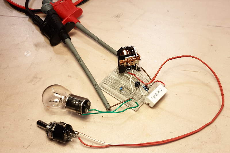
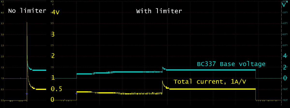
3.5A, while the limiter reduces it to 0.8A which is just slightly above nominal current. A power resistor with smaller value would have reduced this even more.
The green line indicates BC337’s base voltage. You can see that it slowly increases (Oscilloscope accuracy at 40VPP is not the best), and will turn on the relay when current flow (yellow line) has stabilized.
Soft-start circuits / configurable current limiters#
There are dedicated ICs that help soft-starting a system, depending on
- Wattage needs
- Ramp up time
- Slew rate constraints
- Total current limit
In addition, there are different types of inrush current limiters to be selected based on your application:
- Time-controlled: System is fully turned-on after a specified time (simple but dumb)
- Voltage-controlled: System is fully switched on above a voltage trigger level (still simple, medium cost)
- Current-controlled: Limits system current or switches system fully on based on current trigger level (likely more expensive)
Thus, a fitting IC is to be selected. They may be called Power Supervisors, IC soft starter, Supervisor & Reset IC or similar. They may even have internal switching power MOSFETs and use minimal peripheral circuitry. I’ve been working with MAX17562 for my evolution of AnywhereAmps.
Continue reading here: Inrush current limiters - Part2