Configure MAX1756x for your application
Power Supervisor configuration made simple
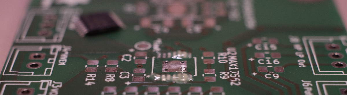 I use MAX17562 ICs in my design for AnywhereAmps Alpha 1.1. For you, I made a quick summary of MAX1756x features and how to configure them. 🙂
Of course, the datasheet you can find on maxim integrated`s page is the master of all information I provide below. I’ll just add some design considerations, details on my way of using it, and provide application proposals.
What are they, again?
MAX1756x is an adjustable overvoltage/ undervoltage and overcurrent protector IC. It is available in three different versions for handling over current events:
- MAX17561: Will turn off in an overcurrent event and autoretry after typically
600ms - MAX17562: Will latch off in an overcurrent event; restart after enable cycle
- MAX17563: Will continue normal operation with current limiter active (dissipates heat)
Both versions are limiting overcurrent events to the configured current limit.
Use my MAX1756x application tool!
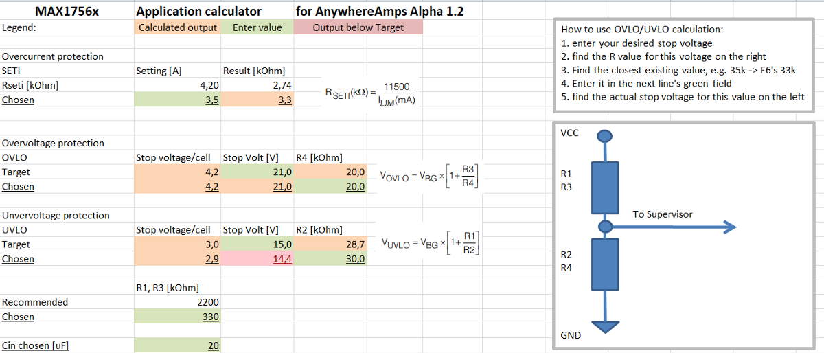 To simplify usage of Max1756x IC in your application, you may use my Max1756x application calculator spreadsheet.1
MAX1756x current limiter / overload detector
The IC features an adjustable current limiter and overcurrent detection (SETI). When current increases above SETI threshold, it is limited to the set value. For MAX17561 and MAX17562: In case this condition remains true for more than typically 20.7ms blanking time, the device will turn off the load circuit. As the MAX17563 will continue normal operation, its power dissipation might lead to over temperature shutdown at some point.
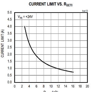
This is how you configure the current limiter / overload detection using the SETI input:
Select a resistor based on the curve on the right (taken from the datasheet) and connect it to SETI and GND. For AnywhereAmps Alpha 1.2, I’m using a 3k3 resistor to get a current limit of ~3.5A.
MAX1756x undervoltage configuration
The IC features undervoltage lockout (UVLO). When voltage decreases below UVLO threshold for typically 16.7ms, the device’s power transistors will switch off the load circuit. Internally, the IC will compare the input voltage at the UVLO pin with the reference voltage Vbg = 1.2V. To set the undervoltage lockout threshold, use a voltage divider to keep UVLO level above Vbg during normal operation.
MAX1756x overvoltage configuration
The IC features overvoltage lockout (OVLO). When voltage increases above OVLO threshold for typically 16.7ms, the device’s power transistors will switch off the load circuit.
It works identical to the undervoltage lockout with the only difference that voltage at the OVLO pin should remain below Vbg under normal operating conditions.
MAX1756x reverse current protection
The IC’s reverse current protection can be enabled by pulling the *RIEN pin to GND. If you intend to use this feature, remember to not accidentally use polarized bypass capacitors like I did at the IC’s input as they will explode if you apply reverse voltage.
Fault *FLAG capability
MAX1756x will indicate a power fault using its *FLAG port under the following conditions:
- Thermal overload
- Overvoltage lockout defined through
OVLO - Reverse current: when reverse current protection
*RIENhas been enabled - Overload current defined through
SETI
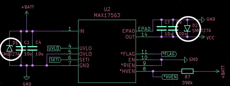
Recommendation: Use TVS diodes
As the datasheet recommends and my experience from incidents in the past shows, I’d use 27V Transient Voltage Suppressor diodes in parallel to both MAX1756x’s input and output ports. It will protect (any inductive) load circuitry from negative voltage spikes on shutdown and the IC itself from surge voltages when connecting a live power supply. Plus, it will clamp reverse input voltage to non-harmful levels.
Recommendation 2: Use non-polarized input capacitors
To mitigate running reset issues when connected to “weak” power supplies or high-resistance input power wiring, use bigger non-polarized input bypass capacitors than you normally would (no, 100nF might not be enough!) - Especially if you drive capacitive or other loads that cause input surge currents.
For more information how to avoid problems here, please read my knowledge blog entry about inrush current limiters.
-
Disclaimer: Although I thorougly read the datasheet and carefully added the data, I can of course take no guarantee whatsoever for the results you yield from this tool. ↩