Vacuum clamping
As I mentioned in the Maker Faire Ruhr 2024 article, I had major problems clamping my workpieces for the production of spirographs.
In this article, I would like to go into this in more detail, analyze the causes and finally present a few possible solutions.
What I can anticipate: All problems can be solved with knowledge of the causes and a little time, planning and material expenditure.
The problem
As usual, I had defined the path planning for the spirographs in such a way that I first had the inner areas (pockets, parts, holes) milled and then the outer areas. Cut-outs and chamfers were to be produced at the very end. I also planned to machine the parts on both sides so that the backs of the gears would also have broken edges and smooth transitions.
Vacuum loss
In my first attempt, I proceeded as I had already successfully done in the spirograph project with the material acrylic glass: The back is machined first, but not milled all the way through. After turning the workpiece, only the chamfer cutter should be used to cut out and break the edges at the same time.
This worked perfectly well for the first clamping.
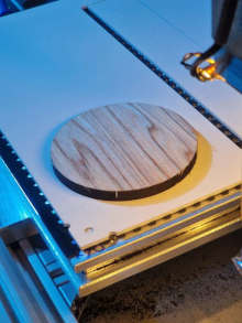
Back machining of the spirographs.
With the second one, however, so much negative pressure was lost when the surface was pierced that the material detached from the vacuum table and took on its original, slight curvature. So I had to stop the milling process and think of another strategy to hold it down.
At this point, I couldn’t really explain why so much more pressure was being lost than during production in acrylic glass.
Cling film
I tried to counteract the pressure loss with cling film. This resulted in several consequential problems: If the cutter passes through the film, it is caught by the cutter when milling closed contours and wrapped around it at lightning speed. The cutter no longer cuts, but only rubs against the material, which very quickly leads to heat marks on the wood.
But even if I attach the cling film in advance: As I cut out parts, the local negative pressure on the part is already so small when it first enters the groove already present on the underside that it can hardly be held in place.
Twisting of the workpiece
For the second attempt, I adapted the strategy: The end mill would mill through the workpiece, so I didn’t need a second set-up. I wanted to optionally realize the edge breaking on the back side later via a holder clamped on the table, into which I would be able to insert the parts.
While cutting out the parts still worked without any problems (again, milling the “inner” parts first), I ran into major problems when applying the chamfer to the front. The gears began to twist and the template with the ring gear could not be held down at all.
Too little time
I therefore had to resort to using holders specially made for the workpieces when machining the front side. Their design and manufacture took time that I had not planned for at this point.
Before the trade fair, I wasn’t able to do an in-depth analysis - a quick solution had to be found.
The causes
With a few weeks’ hindsight, I can now say that several factors led to the problems. A difficult geometry, unfavorable material properties and certain peculiarities of the vacuum table design all came together. But let’s get to the bottom of it all here.
Workpiece
 The raw material is medium density fiberboard of
 10mm thickness. It is covered on one side with 0.75mm thick olive wood veneer. This material is inherently problematic for processing on a vacuum table:
- Due to veneering and storage, the boards are slightly curved1, so they want to stand out from my vacuum table.
- MDF is permeable to air, so the vacuum pump has to deal with larger leakage currents than usual (I only get
300mBarwhen clamping the panel instead of the usual800mBarwithout leakage currents). The low material thickness intensifies this effect. - MDF is not only permeable to air vertically to the panel plane, but also horizontally. This greatly reduces the holding forces in the vicinity of milled grooves, as air can now also penetrate the material laterally, thus additionally increasing the leakage currents.
The video linked here Youtube: Displacement force measurements by Anton CNC clearly shows how different materials behave on a vacuum table with a porous surface. Also highly recommended on this topic is this video YouTube: Determining holding force during machining by vakuumtischDE to get an impression of the load the workpiece can be under during the milling process.
Geometry
My design for the spirographs is not particularly easy to hold down:
- The template with ring gear has thin walls of only about
2cmthickness. They are thickest on the left and right sides, but have a large recess in the middle through which air can penetrate the material in all directions, thus reducing the holding forces. - The gear wheel has holes to accommodate pins. The contact pressure is reduced around the holes.
- The teeth of the ring gear and gearwheel are so exposed that they can make virtually no contribution to the holding force due to cross currents of air in the material. At the same time, however, the tooth heads provide a large lever for twisting or shifting the workpiece: an unfavorable pairing.
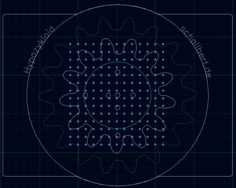
If I take this as a basis for practice, only the vacuum holes inside the circle in the image above are capable of generating any significant clamping forces. However, these are again close to the center and therefore offer little resistance to twisting of the workpiece. In addition, the gear wheel here has several holes and therefore additional “leaks”.
Milling forces
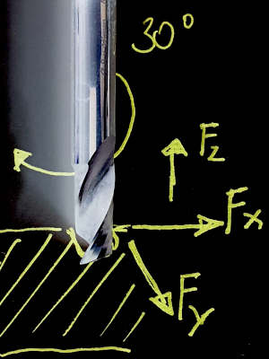 The forces introduced into the material by the tool (the milling cutter) always act in the XY direction and, in the case of V-cut milling cutters and end mills with spiral/twist, also in the Z direction.
- Forces due to feed: The faster the material is moved through, the stronger the forces in the XY direction act on the material in the direction of travel.
- Forces due to cutter rotation (conventional or climb-milling): If an end mill without twist is used, forces are generated orthogonally in the plane of the traverse direction. So if I move in the positive X-direction, the milling cutter will also exert a force in the Y-direction, which is introduced by its own rotation: In conventional milling operation, the cutter wants to avoid the material, so it is deflected towards
Y+(as clearly shown in this article). In the opposite direction, the deflection direction is inverse and the cutter wants to deflect towardsY-. - Forces due to cutter geometry: If the cutter has a spiral or is angled in its geometry, additional forces act in the Z direction. With Vcut and downcut cutters, the material is pressed onto the machine bed, whereas with upcut spiral cutters, the chip is ejected as desired. However, the workpiece also experiences a force that can lift it off the machine bed in extreme cases.
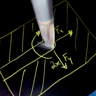
- If milling is carried out in the full groove (i.e. the milling cutter is engaged over its entire diameter instead of moving along the edge of the workpiece), the forces transverse to the milling direction increase even more: In the image, it moves in the opposite direction at the upper edge of the groove, which pushes the milling cutter “away from the material”, i.e. downwards in the image. At the same time, it moves in synchronization at the lower edge of the groove, which pulls it “into the material” - also downwards.
Vacuum clamping system
As described in the articles about vacuum pumps and vacuum tables, I have a dry-running rotary vane pump connected to a perforated grid vacuum table. When processing porous materials, this combination is just as problematic as grid vacuum tables with small-volume pumps:
- My hole-grid vacuum table has blind holes with a vacuum channel of
0.5mmdiameter in their center. This constriction relieves the pump when holes are uncovered, as it does not have to provide the full air flow that the5mmbore allows. However, the hole can build up less negative pressure due to its limited air flow in combination with MDF. - Due to the high leakage currents, my vacuum pump is at its limit with its volume flow. Other pump types are much better suited here (see radial blower, side channel compressor).
- A vacuum table generally only clamps downwards (in the Z direction). However, forces in the XY direction must also be absorbed to prevent the workpiece from shifting or rotating. These are coupled to the vacuum on the workpiece via the coefficient of static friction µ (and can be influenced by material pairing and surface properties), but if the latter is too low, the workpiece is not held reliably.
- Although the vacuum channels are located in a
10mmgrid, the distance relevant for the leakage flow is only5mm. This is because the edges of the blind holes (each5mmin diameter) are at this distance from each other, so that the air flow has to travel a shorter distance across the material than through it.
Comparison with the resistance network
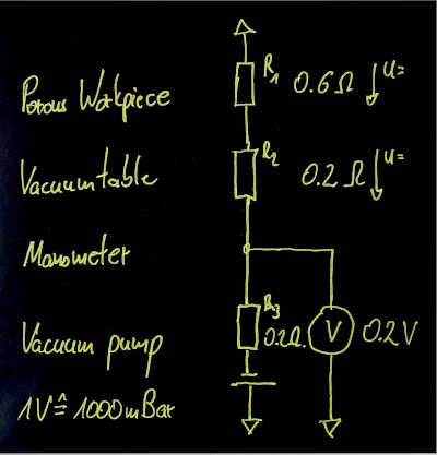
The actual clamping force can be easily estimated by imagining the pump, vacuum table and workpiece as an electrical network. I have prepared a model for this and present it below.
Resistors: Vacuum table, workpiece
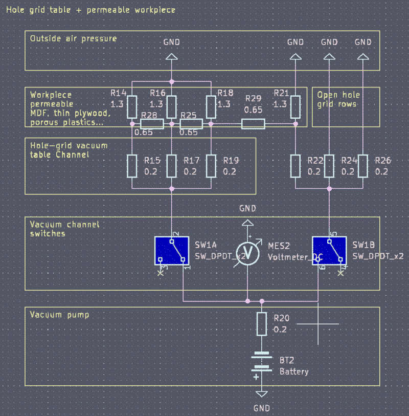
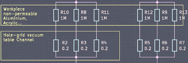 The suction holes of the vacuum table represent resistors for the air flow, which are connected in parallel. The workpiece is again connected in series as a resistor, which is connected with its other pole to “ground”, i.e. the ambient air pressure.
Vacuum manifold = switch, pressure gauge = voltmeter
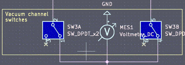 The pressure gauge in the suction channel can be seen as a voltage meter. I take the vacuum distributor with its valves for switching the vacuum sections as an electrical switching device. If the switch is closed, it establishes the connection between pump and vacuum table. If it is open, it blocks the air flow.
Vacuum pump = voltage source
In this picture, the pump represents a voltage source, which in my case can provide a maximum of U = 8V corresponding to -800mBar. Due to the internal resistance of 0.2Ohm present in real voltage sources, it can generate a short-circuit current of I = 40A, analogous to the 40m³/h flow rate. This comparison is of course not physically correct, because I would have to work with mass flows instead of volume flows. In addition, the flow rate is not linearly related to the pressure everywhere in the characteristic diagram and the resistance values I have assumed are only reference values. In my opinion, it is nevertheless suitable for modeling the situation under steady-state conditions.
With workpiece materials such as acrylic glass or metal, the air flow is close to zero, so their “resistance” is extremely high. This causes most of the tension (negative pressure) to drop here, so that the workpiece is firmly clamped.
When using airtight materials, all is well with the world: the pressure gauge correctly indicates the pressure on the material when the workpiece is still unprocessed. Even in the case of milled holes, only the resistance of the material “in series” to the affected suction holes is set to zero. This means that the negative pressure and therefore the holding force on the part itself is hardly reduced.
If you look closely, you can see that the pressure gauge measures the pressure difference upstream of the vacuum manifold. Its value is therefore only meaningful for the clamping force if the workpiece has a very high flow resistance.
Special case of porous materials
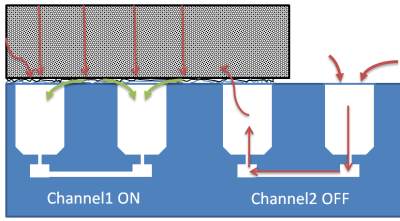
The situation is completely different with porous materials such as MDF:
Here, the contact resistance of the material is only just an order of magnitude higher than that of the vacuum holes. I determined the values through tests on the vacuum table. They are based on pressure measurements, calculations of the workpiece surface, and the number of active suction holes covered by the material. Two effects should be particularly emphasized here, which made holding down even more difficult for me:
- Pay attention to the resistances in the material in parallel to the contact resistance in the
Z direction. They are caused by the fact that the air can now also move through the material “between the holes”. - On the right-hand side of the picture you can see what happens when the workpiece protrudes into an inactive vacuum area: The suction holes are connected to each other with virtually no resistance by means of vacuum channels in the table. As the workpiece allows “transverse air flow” in the
XYdirection, significantly less resistance has to be overcome by connecting the suction holes than for penetration in theZdirection. This means that onlyR29andR22||R21are still in series. If the workpiece covers several inactive hole fields,R22approaches 0.
As a result, the resistances upstream of R19, namely R18||(R29+(R21||R22)), become so small that the pump practically only draws ambient air here and can hardly apply any clamping force at this point. The cross air flow also affects the pressure drop of R17, R15 via R25.
Now the small suction holes act as voltage dividers, so that a not inconsiderable part of the negative pressure “sticks” to them.
This means that the pressure displayed on the pressure gauge no longer corresponds to the conditions on the workpiece: Although I still get -200mBar displayed here, the clamping force is reduced precisely at the most sensitive points for holding down
- at the edge of the workpiece
- in areas adjacent to those where the workpiece is not actively sucked in
- as well as at every through-milling and a certain radius
to almost zero.
For all other areas, Kirchhoff’s laws apply: A voltage divider is formed consisting of the pump’s internal resistance, the vacuum system and the penetration resistance of the workpiece. Only the voltage still on the workpiece determines the hold-down force. It is - I repeat myself now - possibly much lower than a glance at the pressure gauge would suggest.
Solutions
Quite a lot of theory for the banal realization that the workpiece is twisted on the machine bed, isn’t it? I have the following solutions in my quiver for such a problem:
Pump / vacuum table
When working with porous materials, it is important that the table itself has a low flow resistance. This is the only way to ensure that the majority of the negative pressure falls on the workpiece, resulting in a higher clamping force. According to the motto “a lot helps a lot”, a pump with a higher flow rate, a table with larger suction openings and a vacuum distributor with larger hose diameters would be appropriate here. However, this is out of question for me.
Adhesion agent
I could try using a coarser-meshed rubber mat. With a 20mm hole pattern, the resistance for the cross air flow is tripled, so that the outer areas are no longer affected by the pressure loss to such an extent. Such a mat also has more rubber surface area, which increases static friction.
Adhesive tape instead of cling film on the material surface solves the problem of catching in the cutter and closes the pores of the material locally, which can improve the holding force in critical areas.
Of course, conventional methods such as applying double-sided adhesive tape or screwing down the workpiece can also be used on a vacuum table. But I don’t do that - because then I would have to admit to myself that my vacuum table is not suitable for all cases.
Fixture and taps
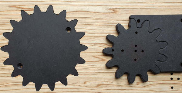 This solution aims to prevent the workpiece from twisting and shifting. The vacuum table is only used here to hold down the workpiece, while a suitably manufactured holder absorbs forces in the ‘XY direction’. The picture shows holders for the template and the gear wheel, which fulfill this task. They are attached to the machine bed and require a precise zero point in order to be able to break the workpieces edges without misalignment.
I use a clearance fit with 0.1mm between the components. If the clearance is smaller, I need too much force to insert. If I use larger values, the workpieces can be twisted too much.
With this variant, I can straighten warped workpieces, continue to produce very fine engravings and still make sure that nothing slips.
The disadvantages are time and material required for planning and producing individual fixtures or templates.
Modification of the workpiece
This is obvious: I can change the properties of the workpiece so that it becomes impermeable to air. For example, I can cover the underside with a film to improve the static friction.
If, like me, you don’t like using plastic: I have found that baking paper / cling film made from unbleached cellulose hardly lets any air through. I’ll soon be trying out covering materials or covering areas affected by milling with it instead of plastic film.
-
If such a problem occurs regularly, grid vacuum tables with a sealing cord are an excellent solution: Here, a linear seal is used to seal the outer edges of the workpiece against the ambient air pressure so that the edges of the workpiece have no chance of curving upwards. With my perforated grid table, however, the entire surface of the rubber mat acts as a seal, so that the curvature is in the form of a contact line on the mat. However, lines do not have a surface area, and my table can only hold down through this. Incidentally, this is also the reason why flexible materials such as films can be pulled off the vacuum table so easily. ↩